Click here
-
Function Overview
-
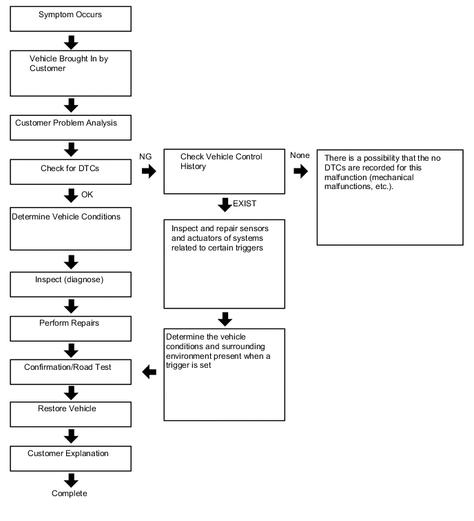
The vehicle control history is a function that records control data (record data) when triggered by specific vehicle behavior. When DTCs are not detected according to information provided by customers, by checking the vehicle control history, it is possible to gain a quantitative grasp on diagnostic information and the history can be used as a reference to proceed with malfunction diagnosis.
-
The vehicle control history is recorded in different storage areas designated by trigger group and it is possible to save up to 140 items in total. If storage space runs out, the data is cleared from the oldest data first for the respective storage area and new data is recorded.
-
Each trigger receives time information from the main body ECU (time elapsed since power switch turned on (IG)) or the navigation system* (absolute time).
-
*: Only for factory-installed navigation systems (factory option)
-
-
Data is recorded in the airbag sensor assembly EEPROM. Even if the negative (-) auxiliary battery terminal is disconnected, the vehicle control history does not disappear. Also, data cannot be cleared using the GTS.
-
-
Notices for Use
-
Vehicle control history is used as support information during malfunction diagnosis for each system and cannot be used to determine the actual cause of a problem.
-
Judgment of each trigger is based on signals from sensors and actuators (recognition value of each ECU). Therefore, make sure to inspect and adjust systems related to each trigger when using the vehicle control history.
Basic Flow
-
-
Trigger Item
-
Connect the GTS to the DLC3.
-
Turn the power switch on (IG).
-
Using the GTS, enter the following menus: Body Electrical / SRS Airbag / Utility / Vehicle Control History.
- Body Electrical > SRS Airbag > Utility
Tester Display Vehicle Control History -
-
-
-
Table 1. Trigger Item Chart Related System Storage Area Group (storage limit) Trigger Item Name Trigger Description Remarks Engine control/Hybrid control/Automatic transmission Area 2
(Approximately 42 times)
Accelerator pedal opening angle signal is high during low speed An accelerator high position signal condition continues for a certain period of time while in the low speed range. - Accelerator pedal opening angle signal is high immediately after brake pedal is released An accelerator high position signal is received while in the low speed range after there is a change from brake input condition to brake and accelerator pedal released condition. - Area 7
(Approximately 12 times)
Accelerator high position in mid to high speed An accelerator high position signal condition continues for a certain period of time while in the mid to high speed range. - Engine control/Hybrid control/Automatic transmission Area 3
(Approximately 40 times)
Accelerator pedal opening angle is medium or higher immediately after shifting to R An accelerator mid to high position signal is received while in the low speed range immediately after the shift lever is moved to R during an accelerator low position signal condition. Excluding hybrid vehicles Accelerator pedal opening angle is medium or higher immediately after shifting to forward position An accelerator mid to high position signal is received while in the low speed range immediately after the shift lever is moved to a forward position (a position other than P, N or R) during an accelerator low position signal condition. Excluding hybrid vehicles Accelerator pedal opening angle is medium or higher immediately after shifting to driving position An accelerator mid to high position signal is received while in the low speed range immediately after the shift lever is moved to a driving position (a position other than P or N) during an accelerator low position signal condition. Only hybrid vehicles R position signal input during medium or higher accelerator signal input An accelerator mid to high position signal condition while the shift lever is in R continues for a certain period of time after the shift lever is moved to R during an accelerator mid to high position signal condition. Excluding hybrid vehicles Forward position signal input during medium or higher accelerator signal input An accelerator mid to high position signal condition continues for a certain period of time while in a forward position (a position other than P, N or R) after shifting to a forward position (a position other than P, N, or R) during an accelerator mid to high position signal condition. Excluding hybrid vehicles Engine control/Hybrid control/Automatic transmission Area 3
(Approximately 40 times)
Driving position signal input during medium or higher accelerator signal input The shift lever is moved to a driving position (a position other than P or N) during an accelerator mid to high position signal condition. Only hybrid vehicles Accelerator signal and brake signal input simultaneously An accelerator mid to high position signal condition and brake input condition simultaneously continue for a certain period of time. - Medium or higher accelerator signal input immediately after switching to D or R The shift lever is moved to D (or R) during an accelerator low signal condition after the shift lever is moved to R (or D). After that, an accelerator mid to high position signal is received. - Medium or higher accelerator signal input during N An accelerator mid to high position signal is received while in a low speed range after the shift lever is moved to N. - Brake control Area 5
(Approximately 5 times)
VSC operation history When VSC operation starts. Only for vehicles with VSC TRC operation history When TRC operation starts. Only for vehicles with TRC ABS operation history When ABS operation starts. - Area 11
(Approximately 2 times)
SCB operation history The SCB (second crash brake) operates. Only for vehicles with SCB Area 1
(Approximately 4 times)
Sudden braking history Detects forward and backward acceleration above a certain level. Only for vehicles with VSC Sudden turning history Detects lateral acceleration above a certain level. Only for vehicles with VSC Cruise control Area 4
(Approximately 15 times)
Accelerator pedal opening angle signal is high during cruise control operation An accelerator high position signal condition continues for a certain period of time during cruise control. Only for vehicles with cruise control Stop assist history (shift to deceleration phase) Stop support function operation history (decelerating stop transition). Only for vehicles with stop assist function Stop assist history (shift to stop phase) Stop support function operation history (stop hold transition). Only for vehicles with stop assist function Stop assist history (cancelation from warning phase) Stop support function operation history (cancellation from warning phase). Only for vehicles with stop assist function Stop assist history (cancelation from speed restraint phase) Stop support function operation history (cancellation from speed control phase). Only for vehicles with stop assist function Stop assist history (cancelation from deceleration phase) Stop support function operation history (cancellation from decelerating stop phase). Only for vehicles with stop assist function Stop assist history (cancelation from stop phase) Stop support function operation history (cancellation from stopped on hold phase). Only for vehicles with stop assist function Pre-collision Area 6
(Approximately 10 times)
PCS operation history (warning buzzer operation) PCS (warning buzzer) operates. Only for vehicles with PCS PCS operation history (warning brake operation) PCS (brake alarm) operates. Only for vehicles with PCS (w/ Driver Monitor Camera) PCS operation history (pre-collision brake assist operation) PCS (PCS brake assist) operates. Only for vehicles with PCS PCS operation history (prior brake operation) PCS (preliminary braking) operates. Only for vehicles with PCS PCS operation history (pre-collision brake operation) PCS (PCS brake) operates. Only for vehicles with PCS PCS operation history (pre-collision seat belt operation) PCS (PCS seat belt) operates. Only for vehicles with PCS PCS operation history (pre-pump operation) PCS (PCS brake assist standby) operates. Only for vehicles with PCS PCS operation history (PBR operation) PCS (stop light illumination) operates. Only for vehicles with PCS PCS operation history (PBH operation) PCS (after operation brake hold) operates. Only for vehicles with PCS PCS operation history (avoidance support) PCS (evasion support) operates. Only for vehicles with PCS PCS operation history (when acceleration above certain amount is detected) Forward and backward acceleration above a certain amount is detected. Only for vehicles with PCS PCS operation history (request combined steering) Steering assist is requested. Only for vehicles with PCS PCS operation history (caution operation) PCS warning operates. Only for vehicles with PCS Pedestrian protection system over constant pressure sensor signal input Pressure sensor signal input above a certain amount is detected. Only for vehicles with Pedestrian Protection System PCS operation history (side airbag operation request) Side airbag prevention-linked function operates. Only for vehicles with PCS Lane departure alert/Lane-keeping assist Area 8
(Approximately 12 times)
Torque sensor signal above certain amount is detected during LKA/LDA operation When the LKA/LDA/LTA system is ON, a torque sensor signal above a certain amount is detected. Only for vehicles with LKA/LDA (w/ Steering Control)/LTA Lane change assist operation history Lane change assist operates. Only for vehicles with LCA Intelligent clearance sonar Area 9
(Approximately 6 times)
ICS operation history (output limit) ICS (output restriction) operates. Only for vehicles with ICS ICS operation history (max output limit) ICS (maximum output restriction) operates. Only for vehicles with ICS ICS operation history (brake control) ICS (brake control) operates. Only for vehicles with ICS ICS operation history (stop) ICS (vehicle stop) operates. Only for vehicles with ICS ICS operation history (regression) ICS (return) operates. Only for vehicles with ICS ICS operation history (temporarily not available) ICS is temporarily not available. Only for vehicles with ICS FHL Area 10
(Approximately 3 times)
FHL operation history Proximity warning for rear vehicles operates. Only for vehicles with FHL - Body Electrical > SRS Airbag > Utility
-
-
Record Data Items
-
When a trigger is detected, the vehicle status (ECU data) before and after the trigger are simultaneously recorded as record data.
-
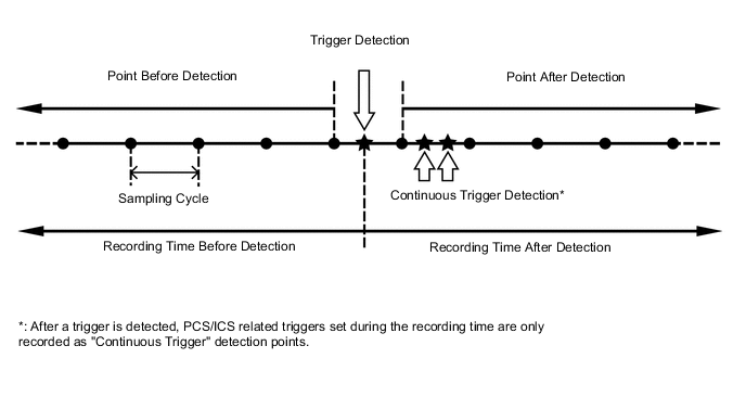
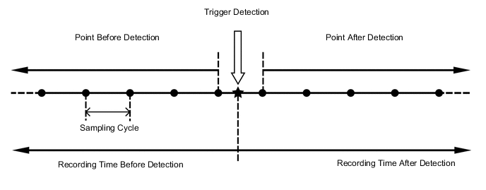
Recording time and record data differ for each trigger.
When not "PCS/ICS Operation History"
When "PCS/ICS Operation History"
Table 2. Record Data Specifications Trigger Item Record Data Before Detection After Detection Sampling Cycle (sec.) ID No. Item Recording Time (sec.) Number of Points Recording Time (sec.) Number of Points 2 Accelerator pedal opening angle signal is high during low speed 7.5 15 7.5 16 0.5 3 Accelerator high position in mid to high speed 7.5 15 7.5 16 0.5 4 Accelerator pedal opening angle signal is high immediately after brake pedal is released 7.5 15 7.5 16 0.5 5-1 Accelerator pedal opening angle is medium or higher immediately after shifting to R 5 10 5 11 0.5 5-2 Accelerator pedal opening angle is medium or higher immediately after shifting to forward position 5-3 Accelerator pedal opening angle is medium or higher immediately after shifting to driving position 6-1 R position signal input during medium or higher accelerator signal input 5 10 5 11 0.5 6-2 Forward position signal input during medium or higher accelerator signal input 6-3 Driving position signal input during medium or higher accelerator signal input 8 Accelerator signal and brake signal input simultaneously 5 10 5 11 0.5 9 Medium or higher accelerator signal input immediately after switching to D or R 5 10 5 11 0.5 10 Medium or higher accelerator signal input during N 5 10 5 11 0.5 12 VSC operation history 5 34 5 35 0.15 13 TRC operation history 5 34 5 35 0.15 14 ABS operation history 5 34 5 35 0.15 15 Sudden braking history 5 34 5 35 0.15 16 Sudden turning history 5 34 5 35 0.15 17 Accelerator pedal opening angle signal is high during cruise control operation 5 10 5 11 0.5 18-1 PCS operation history (warning buzzer operation) 5 10 4 9 0.5 18-2 PCS operation history (warning brake operation) 18-3 PCS operation history (pre-collision brake assist operation) 18-4 PCS operation history (prior brake operation) 18-5 PCS operation history (pre-collision brake operation) 18-6 PCS operation history (pre-collision seat belt operation) 18-7 PCS operation history (pre-pump operation) 18-8 PCS operation history (PBR operation) 18-9 PCS operation history (PBH operation) 18-10 PCS operation history (avoidance support) 18-11 PCS operation history (when acceleration above certain amount is detected) 18-12 PCS operation history (request combined steering) 18-13 PCS operation history (caution operation) 18-14 Pedestrian protection system over constant pressure sensor signal input 18-15 PCS operation history (side airbag operation request) 19 Torque sensor signal above certain amount is detected during LKA/LDA operation 8 20 0 1 0.4 20-1 ICS operation history (output limit) 5 10 5 11 0.5 20-2 ICS operation history (max output limit) 20-3 ICS operation history (brake control) 20-4 ICS operation history (stop) 20-5 ICS operation history (regression) 20-6 ICS operation history (temporarily not available) 22 Lane change assist operation history 8 20 0 1 0.4 23 FHL operation history 5 25 3 16 0.2 24 SCB operation history 5 34 5 35 0.15 26-1 Stop assist history (shift to deceleration phase) 2 4 5 11 0.5 26-2 Stop assist history (shift to stop phase) 26-3 Stop assist history (cancelation from warning phase) 26-4 Stop assist history (cancelation from speed restraint phase) 26-5 Stop assist history (cancelation from deceleration phase) 26-6 Stop assist history (cancelation from stop phase) Table 3. Record Data Chart Item Name Trigger ID No. Vehicle Speed 2, 3, 4, 5-1, 5-2, 5-3, 6-1, 6-2, 6-3, 8, 9, 10, 12, 13, 14, 15, 16, 17, 18-1, 18-2, 18-3, 18-4, 18-5, 18-6, 18-7, 18-8, 18-9, 18-10, 18-11, 18-12, 18-13, 18-14, 18-15, 19, 20-1, 20-2, 20-3, 20-4, 20-5, 20-6, 22, 23, 24, 26-1, 26-2, 26-3, 26-4, 26-5, 26-6 Accelerator Opening Ratio 2, 3, 4, 5-1, 5-2, 5-3, 6-1, 6-2, 6-3, 8, 9, 10, 12, 13, 14, 15, 16, 17, 18-1, 18-2, 18-3, 18-4, 18-5, 18-6, 18-7, 18-8, 18-9, 18-10, 18-11, 18-12, 18-13, 18-14, 18-15, 19, 20-1, 20-2, 20-3, 20-4, 20-5, 20-6, 22, 23, 24, 26-1, 26-2, 26-3, 26-4, 26-5, 26-6 Engine RPM Data 2, 3, 4, 5-1, 5-2, 5-3, 6-1, 6-2, 6-3, 8, 9, 10, 12, 13, 14, 15, 16, 17, 18-1, 18-2, 18-3, 18-4, 18-5, 18-6, 18-7, 18-8, 18-9, 18-10, 18-11, 18-12, 18-13, 18-14, 18-15, 19, 20-1, 20-2, 20-3, 20-4, 20-5, 20-6, 22, 23, 24, 26-1, 26-2, 26-3, 26-4, 26-5, 26-6 Cruise Control 2, 3, 4, 5-1, 5-2, 5-3, 6-1, 6-2, 6-3, 8, 9, 10, 12, 13, 14, 15, 16, 17, 18-1, 18-2, 18-3, 18-4, 18-5, 18-6, 18-7, 18-8, 18-9, 18-10, 18-11, 18-12, 18-13, 18-14, 18-15, 19, 20-1, 20-2, 20-3, 20-4, 20-5, 20-6, 22, 23, 24, 26-1, 26-2, 26-3, 26-4, 26-5, 26-6 Shift Position Signal 2, 3, 4, 5-1, 5-2, 5-3, 6-1, 6-2, 6-3, 8, 9, 10, 12, 13, 14, 15, 16, 17, 18-1, 18-2, 18-3, 18-4, 18-5, 18-6, 18-7, 18-8, 18-9, 18-10, 18-11, 18-12, 18-13, 18-14, 18-15, 19, 20-1, 20-2, 20-3, 20-4, 20-5, 20-6, 22, 23, 24, 26-1, 26-2, 26-3, 26-4, 26-5, 26-6 Brake SW 2, 3, 4, 5-1, 5-2, 5-3, 6-1, 6-2, 6-3, 8, 9, 10, 12, 13, 14, 15, 16, 17, 18-1, 18-2, 18-3, 18-4, 18-5, 18-6, 18-7, 18-8, 18-9, 18-10, 18-11, 18-12, 18-13, 18-14, 18-15, 19, 20-1, 20-2, 20-3, 20-4, 20-5, 20-6, 22, 23, 24, 26-1, 26-2, 26-3, 26-4, 26-5, 26-6 Brake Oil Pressure 2, 3, 4, 5-1, 5-2, 5-3, 6-1, 6-2, 6-3, 8, 9, 10, 12, 13, 14, 15, 16, 17, 18-1, 18-2, 18-3, 18-4, 18-5, 18-6, 18-7, 18-8, 18-9, 18-10, 18-11, 18-12, 18-13, 18-14, 18-15, 19, 20-1, 20-2, 20-3, 20-4, 20-5, 20-6, 22, 23, 24, 26-1, 26-2, 26-3, 26-4, 26-5, 26-6 Yaw Rate Sensor Signal 2, 3, 4, 5-1, 5-2, 5-3, 6-1, 6-2, 6-3, 8, 9, 10, 12, 13, 14, 15, 16, 17, 18-1, 18-2, 18-3, 18-4, 18-5, 18-6, 18-7, 18-8, 18-9, 18-10, 18-11, 18-12, 18-13, 18-14, 18-15, 19, 20-1, 20-2, 20-3, 20-4, 20-5, 20-6, 22, 23, 24, 26-1, 26-2, 26-3, 26-4, 26-5, 26-6 Longitudinal G Sensor Signal 2, 3, 4, 5-1, 5-2, 5-3, 6-1, 6-2, 6-3, 8, 9, 10, 12, 13, 14, 15, 16, 17, 18-1, 18-2, 18-3, 18-4, 18-5, 18-6, 18-7, 18-8, 18-9, 18-10, 18-11, 18-12, 18-13, 18-14, 18-15, 19, 20-1, 20-2, 20-3, 20-4, 20-5, 20-6, 22, 23, 24, 26-1, 26-2, 26-3, 26-4, 26-5, 26-6 Lateral G Sensor Signal 2, 3, 4, 5-1, 5-2, 5-3, 6-1, 6-2, 6-3, 8, 9, 10, 12, 13, 14, 15, 16, 17, 18-1, 18-2, 18-3, 18-4, 18-5, 18-6, 18-7, 18-8, 18-9, 18-10, 18-11, 18-12, 18-13, 18-14, 18-15, 19, 20-1, 20-2, 20-3, 20-4, 20-5, 20-6, 22, 23, 24, 26-1, 26-2, 26-3, 26-4, 26-5, 26-6 Throttle Opening Ratio 2, 3, 4, 5-1, 5-2, 5-3, 6-1, 6-2, 6-3, 8, 9, 10, 12, 13, 14, 15, 16, 17, 18-1, 18-2, 18-3, 18-4, 18-5, 18-6, 18-7, 18-8, 18-9, 18-10, 18-11, 18-12, 18-13, 18-14, 18-15, 19, 20-1, 20-2, 20-3, 20-4, 20-5, 20-6, 22, 23, 24, 26-1, 26-2, 26-3, 26-4, 26-5, 26-6 Command Value of Fuel Injection Amount 2, 3, 4, 5-1, 5-2, 5-3, 6-1, 6-2, 6-3, 8, 9, 10, 12, 13, 14, 15, 16, 17, 18-1, 18-2, 18-3, 18-4, 18-5, 18-6, 18-7, 18-8, 18-9, 18-10, 18-11, 18-12, 18-13, 18-14, 18-15, 19, 20-1, 20-2, 20-3, 20-4, 20-5, 20-6, 22, 23, 24, 26-1, 26-2, 26-3, 26-4, 26-5, 26-6 Steering Signal 2, 3, 4, 5-1, 5-2, 5-3, 6-1, 6-2, 6-3, 8, 9, 10, 12, 13, 14, 15, 16, 17, 18-1, 18-2, 18-3, 18-4, 18-5, 18-6, 18-7, 18-8, 18-9, 18-10, 18-11, 18-12, 18-13, 18-14, 18-15, 19, 20-1, 20-2, 20-3, 20-4, 20-5, 20-6, 22, 23, 24, 26-1, 26-2, 26-3, 26-4, 26-5, 26-6 HV Recognition Flag 2, 3, 4, 5-1, 5-2, 5-3, 6-1, 6-2, 6-3, 8, 9, 10, 12, 13, 14, 15, 16, 17, 18-1, 18-2, 18-3, 18-4, 18-5, 18-6, 18-7, 18-8, 18-9, 18-10, 18-11, 18-12, 18-13, 18-14, 18-15, 19, 20-1, 20-2, 20-3, 20-4, 20-5, 20-6, 22, 23, 24, 26-1, 26-2, 26-3, 26-4, 26-5, 26-6 Diesel Flag 2, 3, 4, 5-1, 5-2, 5-3, 6-1, 6-2, 6-3, 8, 9, 10, 12, 13, 14, 15, 16, 17, 18-1, 18-2, 18-3, 18-4, 18-5, 18-6, 18-7, 18-8, 18-9, 18-10, 18-11, 18-12, 18-13, 18-14, 18-15, 19, 20-1, 20-2, 20-3, 20-4, 20-5, 20-6, 22, 23, 24, 26-1, 26-2, 26-3, 26-4, 26-5, 26-6 Sensor Type Identification (Security) 2, 3, 4, 5-1, 5-2, 5-3, 6-1, 6-2, 6-3, 8, 9, 10, 12, 13, 14, 15, 16, 17, 18-1, 18-2, 18-3, 18-4, 18-5, 18-6, 18-7, 18-8, 18-9, 18-10, 18-11, 18-12, 18-13, 18-14, 18-15, 19, 20-1, 20-2, 20-3, 20-4, 20-5, 20-6, 22, 23, 24, 26-1, 26-2, 26-3, 26-4, 26-5, 26-6 Sensor Type Identification (G Sensor Layout) 2, 3, 4, 5-1, 5-2, 5-3, 6-1, 6-2, 6-3, 8, 9, 10, 12, 13, 14, 15, 16, 17, 18-1, 18-2, 18-3, 18-4, 18-5, 18-6, 18-7, 18-8, 18-9, 18-10, 18-11, 18-12, 18-13, 18-14, 18-15, 19, 20-1, 20-2, 20-3, 20-4, 20-5, 20-6, 22, 23, 24, 26-1, 26-2, 26-3, 26-4, 26-5, 26-6 Sensor Type Identification (G Sensor) 2, 3, 4, 5-1, 5-2, 5-3, 6-1, 6-2, 6-3, 8, 9, 10, 12, 13, 14, 15, 16, 17, 18-1, 18-2, 18-3, 18-4, 18-5, 18-6, 18-7, 18-8, 18-9, 18-10, 18-11, 18-12, 18-13, 18-14, 18-15, 19, 20-1, 20-2, 20-3, 20-4, 20-5, 20-6, 22, 23, 24, 26-1, 26-2, 26-3, 26-4, 26-5, 26-6 Sensor Type Identification (Yaw Rate Sensor) 2, 3, 4, 5-1, 5-2, 5-3, 6-1, 6-2, 6-3, 8, 9, 10, 12, 13, 14, 15, 16, 17, 18-1, 18-2, 18-3, 18-4, 18-5, 18-6, 18-7, 18-8, 18-9, 18-10, 18-11, 18-12, 18-13, 18-14, 18-15, 19, 20-1, 20-2, 20-3, 20-4, 20-5, 20-6, 22, 23, 24, 26-1, 26-2, 26-3, 26-4, 26-5, 26-6 Yaw G Sensor Installation Information 2, 3, 4, 5-1, 5-2, 5-3, 6-1, 6-2, 6-3, 8, 9, 10, 12, 13, 14, 15, 16, 17, 18-1, 18-2, 18-3, 18-4, 18-5, 18-6, 18-7, 18-8, 18-9, 18-10, 18-11, 18-12, 18-13, 18-14, 18-15, 19, 20-1, 20-2, 20-3, 20-4, 20-5, 20-6, 22, 23, 24, 26-1, 26-2, 26-3, 26-4, 26-5, 26-6 Shift Gear 2, 3, 4, 5-1, 5-2, 5-3, 6-1, 6-2, 6-3, 8, 9, 10, 12, 13, 15, 16 Power Train Mode 2, 3, 4, 5-1, 5-2, 5-3, 6-1, 6-2, 6-3, 8, 9, 10, 12, 13, 15, 16 SNOW Mode 2, 3, 4, 5-1, 5-2, 5-3, 6-1, 6-2, 6-3, 8, 9, 10, 12, 13, 15, 16 Valid/Invalid of Driving Mode 2, 3, 4, 5-1, 5-2, 5-3, 6-1, 6-2, 6-3, 8, 9, 10, 12, 13, 15, 16 VSC OFF Lamp 2, 3, 4, 5-1, 5-2, 5-3, 6-1, 6-2, 6-3, 8, 9, 10, 12, 13, 15, 16 TRC OFF Lamp 2, 3, 4, 5-1, 5-2, 5-3, 6-1, 6-2, 6-3, 8, 9, 10, 12, 13, 15, 16 Valid/Invalid of TRC/VSC OFF Lamp 2, 3, 4, 5-1, 5-2, 5-3, 6-1, 6-2, 6-3, 8, 9, 10, 12, 13, 15, 16 EV Mode 2, 3, 4, 5-1, 5-2, 5-3, 6-1, 6-2, 6-3, 8, 9, 10, 12, 13, 15, 16 Valid/Invalid of EV Mode 2, 3, 4, 5-1, 5-2, 5-3, 6-1, 6-2, 6-3, 8, 9, 10, 12, 13, 15, 16 Drive Mode Select Signal 2, 3, 4, 5-1, 5-2, 5-3, 6-1, 6-2, 6-3, 8, 9, 10, 12, 13, 15, 16 Engine Load Factor 2, 3, 4, 5-1, 5-2, 5-3, 6-1, 6-2, 6-3, 8, 9, 10 READY Signal 2, 3, 4, 5-1, 5-2, 5-3, 6-1, 6-2, 6-3, 8, 9, 10, 12, 13, 15, 16 Gear Position Signal 2, 3, 4, 5-1, 5-2, 5-3, 6-1, 6-2, 6-3, 8, 9, 10, 15, 16 Turbine RPM/Input Shaft RPM 2, 3, 4, 5-1, 5-2, 5-3, 6-1, 6-2, 6-3, 8, 9, 10, 15, 16 Under DSC Control 5-1, 5-2, 5-3, 6-1, 6-2, 6-3, 8, 9, 10 Under BOS Control 5-1, 5-2, 5-3, 6-1, 6-2, 6-3, 8, 9, 10 Under SCB Control 24 Under VSC Control 12, 13, 14, 15, 16, 24 Under ABS Control 12, 13, 14, 15, 16, 24 Under VDM Control 12, 13, 14, 15, 16, 24 Under TRC Operation Flag 12, 13, 14, 15, 16, 24 FR Wheel Speed 12, 13, 14, 15, 16, 23, 24 FL Wheel Speed 12, 13, 14, 15, 16, 23, 24 RR Wheel Speed 12, 13, 14, 15, 16, 23, 24 RL Wheel Speed 12, 13, 14, 15, 16, 23, 24 Cruise System 17 Driving Force Demand Judgment Flag 17 Cruise Control Master Switch Flag 17 DSS Judgment Flag 17 Cruise Control Res/Accel SW 17 Cruise Control Set/Coast SW 17 Cruise Control Cancel SW 17 Cruise Control Brake SW 17 Cruise Control D Signal 17 Cruise Control Main SW 17 Cruise Control Set Speed 17 Vehicle Speed (during Cruise Control) 17 Cruise Control Request Value 17 ACC Target Distance 17 ACC Target Condition 17 ACC Relative Speed 17 PCS Reception Data Invalid Flag 18-1, 18-2, 18-3, 18-4, 18-5, 18-6, 18-7, 18-8, 18-9, 18-10, 18-11, 18-12, 18-13, 18-14, 18-15 ALM Request Flag 18-1, 18-2, 18-3, 18-4, 18-5, 18-6, 18-7, 18-8, 18-9, 18-10, 18-11, 18-12, 18-13, 18-14, 18-15 ALM Request Flag 2 18-1, 18-2, 18-3, 18-4, 18-5, 18-6, 18-7, 18-8, 18-9, 18-10, 18-11, 18-12, 18-13, 18-14, 18-15 ABK Request Flag 18-1, 18-2, 18-3, 18-4, 18-5, 18-6, 18-7, 18-8, 18-9, 18-10, 18-11, 18-12, 18-13, 18-14, 18-15 PBA Request Flag 18-1, 18-2, 18-3, 18-4, 18-5, 18-6, 18-7, 18-8, 18-9, 18-10, 18-11, 18-12, 18-13, 18-14, 18-15 FPB Request Flag 18-1, 18-2, 18-3, 18-4, 18-5, 18-6, 18-7, 18-8, 18-9, 18-10, 18-11, 18-12, 18-13, 18-14, 18-15 PB Request Flag 18-1, 18-2, 18-3, 18-4, 18-5, 18-6, 18-7, 18-8, 18-9, 18-10, 18-11, 18-12, 18-13, 18-14, 18-15 PSB Request Flag 18-1, 18-2, 18-3, 18-4, 18-5, 18-6, 18-7, 18-8, 18-9, 18-10, 18-11, 18-12, 18-13, 18-14, 18-15 Prefill Request Flag 18-1, 18-2, 18-3, 18-4, 18-5, 18-6, 18-7, 18-8, 18-9, 18-10, 18-11, 18-12, 18-13, 18-14, 18-15 Stop Lamp Lighting Request Flag 18-1, 18-2, 18-3, 18-4, 18-5, 18-6, 18-7, 18-8, 18-9, 18-10, 18-11, 18-12, 18-13, 18-14, 18-15 PCS Brake Hold Request Flag 18-1, 18-2, 18-3, 18-4, 18-5, 18-6, 18-7, 18-8, 18-9, 18-10, 18-11, 18-12, 18-13, 18-14, 18-15 Collision Avoidance Assist Request Flag 1 18-1, 18-2, 18-3, 18-4, 18-5, 18-6, 18-7, 18-8, 18-9, 18-10, 18-11, 18-12, 18-13, 18-14, 18-15 Collision Avoidance Assist Request Flag 2 18-1, 18-2, 18-3, 18-4, 18-5, 18-6, 18-7, 18-8, 18-9, 18-10, 18-11, 18-12, 18-13, 18-14, 18-15 Collision Avoidance Assist Request Flag 3 18-1, 18-2, 18-3, 18-4, 18-5, 18-6, 18-7, 18-8, 18-9, 18-10, 18-11, 18-12, 18-13, 18-14, 18-15 PCS SW 18-1, 18-2, 18-3, 18-4, 18-5, 18-6, 18-7, 18-8, 18-9, 18-10, 18-11, 18-12, 18-13, 18-14, 18-15 PCS Display (Diag Condition) 18-1, 18-2, 18-3, 18-4, 18-5, 18-6, 18-7, 18-8, 18-9, 18-10, 18-11, 18-12, 18-13, 18-14, 18-15 PCS Display (Milli Wave Dirt) 18-1, 18-2, 18-3, 18-4, 18-5, 18-6, 18-7, 18-8, 18-9, 18-10, 18-11, 18-12, 18-13, 18-14, 18-15 PCS Display (Temporarily not available) 18-1, 18-2, 18-3, 18-4, 18-5, 18-6, 18-7, 18-8, 18-9, 18-10, 18-11, 18-12, 18-13, 18-14, 18-15 PCS Display (Sensor Recognition Status) 18-1, 18-2, 18-3, 18-4, 18-5, 18-6, 18-7, 18-8, 18-9, 18-10, 18-11, 18-12, 18-13, 18-14, 18-15 PCS Display (Milli-Meter Wave Radar Low Voltage Status) 18-1, 18-2, 18-3, 18-4, 18-5, 18-6, 18-7, 18-8, 18-9, 18-10, 18-11, 18-12, 18-13, 18-14, 18-15 PCS Display (Camera Backlight Status) 18-1, 18-2, 18-3, 18-4, 18-5, 18-6, 18-7, 18-8, 18-9, 18-10, 18-11, 18-12, 18-13, 18-14, 18-15 PCS Display (Milli-Meter Wave Radar Alignment Flag) 18-1, 18-2, 18-3, 18-4, 18-5, 18-6, 18-7, 18-8, 18-9, 18-10, 18-11, 18-12, 18-13, 18-14, 18-15 PCS Display (Object Recognition Status) 18-1, 18-2, 18-3, 18-4, 18-5, 18-6, 18-7, 18-8, 18-9, 18-10, 18-11, 18-12, 18-13, 18-14, 18-15 PCS Display (Control Status 1) 18-1, 18-2, 18-3, 18-4, 18-5, 18-6, 18-7, 18-8, 18-9, 18-10, 18-11, 18-12, 18-13, 18-14, 18-15 PCS Display (Control Status 2) 18-1, 18-2, 18-3, 18-4, 18-5, 18-6, 18-7, 18-8, 18-9, 18-10, 18-11, 18-12, 18-13, 18-14, 18-15 Target Distance 18-1, 18-2, 18-3, 18-4, 18-5, 18-6, 18-7, 18-8, 18-9, 18-10, 18-11, 18-12, 18-13, 18-14, 18-15 Target Relative Velocity 18-1, 18-2, 18-3, 18-4, 18-5, 18-6, 18-7, 18-8, 18-9, 18-10, 18-11, 18-12, 18-13, 18-14, 18-15 Target Lateral Position 18-1, 18-2, 18-3, 18-4, 18-5, 18-6, 18-7, 18-8, 18-9, 18-10, 18-11, 18-12, 18-13, 18-14, 18-15 Target Object Number 18-1, 18-2, 18-3, 18-4, 18-5, 18-6, 18-7, 18-8, 18-9, 18-10, 18-11, 18-12, 18-13, 18-14, 18-15 Relative Acceleration for Control Target 18-1, 18-2, 18-3, 18-4, 18-5, 18-6, 18-7, 18-8, 18-9, 18-10, 18-11, 18-12, 18-13, 18-14, 18-15 Predicted Time to Collision 1 for Control Target 18-1, 18-2, 18-3, 18-4, 18-5, 18-6, 18-7, 18-8, 18-9, 18-10, 18-11, 18-12, 18-13, 18-14, 18-15 Predicted Time to Collision 2 for Control Target 18-1, 18-2, 18-3, 18-4, 18-5, 18-6, 18-7, 18-8, 18-9, 18-10, 18-11, 18-12, 18-13, 18-14, 18-15 Predicted Time to Collision Status for Control Target 18-1, 18-2, 18-3, 18-4, 18-5, 18-6, 18-7, 18-8, 18-9, 18-10, 18-11, 18-12, 18-13, 18-14, 18-15 Sensor Recognition Status for Control Target 18-1, 18-2, 18-3, 18-4, 18-5, 18-6, 18-7, 18-8, 18-9, 18-10, 18-11, 18-12, 18-13, 18-14, 18-15 Type of the Object for Control Target 18-1, 18-2, 18-3, 18-4, 18-5, 18-6, 18-7, 18-8, 18-9, 18-10, 18-11, 18-12, 18-13, 18-14, 18-15 PCS ALM Mode Status 18-1, 18-2, 18-3, 18-4, 18-5, 18-6, 18-7, 18-8, 18-9, 18-10, 18-11, 18-12, 18-13, 18-14, 18-15 PCS ALM Status 18-1, 18-2, 18-3, 18-4, 18-5, 18-6, 18-7, 18-8, 18-9, 18-10, 18-11, 18-12, 18-13, 18-14, 18-15 PCS Guard Status A 18-1, 18-2, 18-3, 18-4, 18-5, 18-6, 18-7, 18-8, 18-9, 18-10, 18-11, 18-12, 18-13, 18-14, 18-15 PCS Guard Status B 18-1, 18-2, 18-3, 18-4, 18-5, 18-6, 18-7, 18-8, 18-9, 18-10, 18-11, 18-12, 18-13, 18-14, 18-15 PCS Guard Status C 18-1, 18-2, 18-3, 18-4, 18-5, 18-6, 18-7, 18-8, 18-9, 18-10, 18-11, 18-12, 18-13, 18-14, 18-15 Sensor Recognition Status (Vertical Axis Offset Status of Milli-Meter Wave Radar) 18-1, 18-2, 18-3, 18-4, 18-5, 18-6, 18-7, 18-8, 18-9, 18-10, 18-11, 18-12, 18-13, 18-14, 18-15 Sensor Recognition Status (Horizontal Axis Offset Status of Milli-Meter Wave Radar) 18-1, 18-2, 18-3, 18-4, 18-5, 18-6, 18-7, 18-8, 18-9, 18-10, 18-11, 18-12, 18-13, 18-14, 18-15 Estimated Curve Radius 18-1, 18-2, 18-3, 18-4, 18-5, 18-6, 18-7, 18-8, 18-9, 18-10, 18-11, 18-12, 18-13, 18-14, 18-15 Over Constant Longitudinal G Sensor Signal Value Detection 18-1, 18-2, 18-3, 18-4, 18-5, 18-6, 18-7, 18-8, 18-9, 18-10, 18-11, 18-12, 18-13, 18-14, 18-15 Over Constant Lateral G Sensor Signal Value Detection 18-1, 18-2, 18-3, 18-4, 18-5, 18-6, 18-7, 18-8, 18-9, 18-10, 18-11, 18-12, 18-13, 18-14, 18-15 Over Constant RR or RA Value Detection 18-1, 18-2, 18-3, 18-4, 18-5, 18-6, 18-7, 18-8, 18-9, 18-10, 18-11, 18-12, 18-13, 18-14, 18-15 ASP-PCS Reception Data Invalid Flag 18-1, 18-2, 18-3, 18-4, 18-5, 18-6, 18-7, 18-8, 18-9, 18-10, 18-11, 18-12, 18-13, 18-14, 18-15 PST Request Flag 18-1, 18-2, 18-3, 18-4, 18-5, 18-6, 18-7, 18-8, 18-9, 18-10, 18-11, 18-12, 18-13, 18-14, 18-15 CAU Request Flag 18-1, 18-2, 18-3, 18-4, 18-5, 18-6, 18-7, 18-8, 18-9, 18-10, 18-11, 18-12, 18-13, 18-14, 18-15 Kind of PCS System 18-1, 18-2, 18-3, 18-4, 18-5, 18-6, 18-7, 18-8, 18-9, 18-10, 18-11, 18-12, 18-13, 18-14, 18-15 Outside Lane Status 18-1, 18-2, 18-3, 18-4, 18-5, 18-6, 18-7, 18-8, 18-9, 18-10, 18-11, 18-12, 18-13, 18-14, 18-15 SCS Steering Angle 18-1, 18-2, 18-3, 18-4, 18-5, 18-6, 18-7, 18-8, 18-9, 18-10, 18-11, 18-12, 18-13, 18-14, 18-15 Camera Load Face Detection 18-1, 18-2, 18-3, 18-4, 18-5, 18-6, 18-7, 18-8, 18-9, 18-10, 18-11, 18-12, 18-13, 18-14, 18-15 Side Radar Target Object Number 18-1, 18-2, 18-3, 18-4, 18-5, 18-6, 18-7, 18-8, 18-9, 18-10, 18-11, 18-12, 18-13, 18-14, 18-15 CAU Operation Pattern 18-1, 18-2, 18-3, 18-4, 18-5, 18-6, 18-7, 18-8, 18-9, 18-10, 18-11, 18-12, 18-13, 18-14, 18-15 PCS Status2 18-1, 18-2, 18-3, 18-4, 18-5, 18-6, 18-7, 18-8, 18-9, 18-10, 18-11, 18-12, 18-13, 18-14, 18-15 Predicted Time to Collision for Side Radar Control Target 18-1, 18-2, 18-3, 18-4, 18-5, 18-6, 18-7, 18-8, 18-9, 18-10, 18-11, 18-12, 18-13, 18-14, 18-15 Type of the Object for Side Radar Control Target 18-1, 18-2, 18-3, 18-4, 18-5, 18-6, 18-7, 18-8, 18-9, 18-10, 18-11, 18-12, 18-13, 18-14, 18-15 Estimated Cross Time for Side Radar Control Target 18-1, 18-2, 18-3, 18-4, 18-5, 18-6, 18-7, 18-8, 18-9, 18-10, 18-11, 18-12, 18-13, 18-14, 18-15 Caution SW 18-1, 18-2, 18-3, 18-4, 18-5, 18-6, 18-7, 18-8, 18-9, 18-10, 18-11, 18-12, 18-13, 18-14, 18-15 Side Radar Target Relative Velocity X 18-1, 18-2, 18-3, 18-4, 18-5, 18-6, 18-7, 18-8, 18-9, 18-10, 18-11, 18-12, 18-13, 18-14, 18-15 Caution Display 18-1, 18-2, 18-3, 18-4, 18-5, 18-6, 18-7, 18-8, 18-9, 18-10, 18-11, 18-12, 18-13, 18-14, 18-15 Side Radar Target Relative Velocity Y 18-1, 18-2, 18-3, 18-4, 18-5, 18-6, 18-7, 18-8, 18-9, 18-10, 18-11, 18-12, 18-13, 18-14, 18-15 Side Radar Target Distance X 18-1, 18-2, 18-3, 18-4, 18-5, 18-6, 18-7, 18-8, 18-9, 18-10, 18-11, 18-12, 18-13, 18-14, 18-15 Side Radar Target Distance Y 18-1, 18-2, 18-3, 18-4, 18-5, 18-6, 18-7, 18-8, 18-9, 18-10, 18-11, 18-12, 18-13, 18-14, 18-15 Collision Point 18-1, 18-2, 18-3, 18-4, 18-5, 18-6, 18-7, 18-8, 18-9, 18-10, 18-11, 18-12, 18-13, 18-14, 18-15 SDV Request Flag 18-1, 18-2, 18-3, 18-4, 18-5, 18-6, 18-7, 18-8, 18-9, 18-10, 18-11, 18-12, 18-13, 18-14, 18-15 PST Target Lateral Position 18-1, 18-2, 18-3, 18-4, 18-5, 18-6, 18-7, 18-8, 18-9, 18-10, 18-11, 18-12, 18-13, 18-14, 18-15 PST Target Distance 18-1, 18-2, 18-3, 18-4, 18-5, 18-6, 18-7, 18-8, 18-9, 18-10, 18-11, 18-12, 18-13, 18-14, 18-15 PST Target Collision Lateral Position 18-1, 18-2, 18-3, 18-4, 18-5, 18-6, 18-7, 18-8, 18-9, 18-10, 18-11, 18-12, 18-13, 18-14, 18-15 Rear Side Object Status 18-1, 18-2, 18-3, 18-4, 18-5, 18-6, 18-7, 18-8, 18-9, 18-10, 18-11, 18-12, 18-13, 18-14, 18-15 PST ETTC 18-1, 18-2, 18-3, 18-4, 18-5, 18-6, 18-7, 18-8, 18-9, 18-10, 18-11, 18-12, 18-13, 18-14, 18-15 PST Obstacle Status 18-1, 18-2, 18-3, 18-4, 18-5, 18-6, 18-7, 18-8, 18-9, 18-10, 18-11, 18-12, 18-13, 18-14, 18-15 Time to Lane Crossing 18-1, 18-2, 18-3, 18-4, 18-5, 18-6, 18-7, 18-8, 18-9, 18-10, 18-11, 18-12, 18-13, 18-14, 18-15 Pedestrian Protection System Record Trigger Signal 18-1, 18-2, 18-3, 18-4, 18-5, 18-6, 18-7, 18-8, 18-9, 18-10, 18-11, 18-12, 18-13, 18-14, 18-15 Pedestrian Protection System Maximum Pressure Ratio (LH) 18-1, 18-2, 18-3, 18-4, 18-5, 18-6, 18-7, 18-8, 18-9, 18-10, 18-11, 18-12, 18-13, 18-14, 18-15 Pedestrian Protection System Maximum Pressure Ratio (RH) 18-1, 18-2, 18-3, 18-4, 18-5, 18-6, 18-7, 18-8, 18-9, 18-10, 18-11, 18-12, 18-13, 18-14, 18-15 Pedestrian Protection System Vehicle Speed for Calculation 18-1, 18-2, 18-3, 18-4, 18-5, 18-6, 18-7, 18-8, 18-9, 18-10, 18-11, 18-12, 18-13, 18-14, 18-15 Rear Pop-Up Hood ECU Judgment Status 18-1, 18-2, 18-3, 18-4, 18-5, 18-6, 18-7, 18-8, 18-9, 18-10, 18-11, 18-12, 18-13, 18-14, 18-15 Front Pop-Up Hood ECU Judgment Status 18-1, 18-2, 18-3, 18-4, 18-5, 18-6, 18-7, 18-8, 18-9, 18-10, 18-11, 18-12, 18-13, 18-14, 18-15 Pedestrian Protection Airbag ECU Judgment Status 18-1, 18-2, 18-3, 18-4, 18-5, 18-6, 18-7, 18-8, 18-9, 18-10, 18-11, 18-12, 18-13, 18-14, 18-15 LKA DDR Trigger Signal 19 Invalid of LKA DDR Data 19 Steering Wheel Release Condition 19 Steering Operation of LKA 19 Steering Operation of LDA 19 LKA Control Condition (EPS Control) 19 LKA Control Condition 19 Turn Signal Operation 19 EPS Torque Sensor Value 12, 13, 14, 15, 16, 19 LTA Trigger Signal 19 LTA DDR Reception Status 19 LTA Steering Wheel Hold Condition 19 Steering Operation of LTA 19 LTA Control Condition 19 LTA EPS Pinion Angle 19 LTA Leading Vehicle Following 19 LTA Leading Vehicle Departure 19 LCA Trigger Signal 22 LCA Data Reception Status 22 LCA Steering Override Trigger 22 LCA Proximity Warning Trigger 22 LCA Brake Override Trigger 22 LCA Distance of Adjacent Forward Vehicle 22 LCA Relative Speed of Adjacent Forward Vehicle 22 LCA Distance of Adjacent Backward Vehicle 22 LCA Relative Speed of Adjacent Backward Vehicle 22 LCA Distance of Forward Vehicle 22 LCA Relative Speed of Forward Vehicle 22 LCA Control State 22 LCA Judgment (RH) 22 LCA Judgment (LH) 22 Turn Signal State 22 LCA Left Lane Marker Kind 22 LCA Right Lane Marker Kind 22 LCA Left Lane Marker Position 22 LCA Right Lane Marker Position 22 LCA Yaw Angle 22 LCA Curvature 22 ICS Received Data Invalid Flag 20-1, 20-2, 20-3, 20-4, 20-5, 20-6 ICS Trigger Flag 20-1, 20-2, 20-3, 20-4, 20-5, 20-6 ICS Temporarily Not Available (Low Voltage) 20-1, 20-2, 20-3, 20-4, 20-5, 20-6 ICS Temporarily Not Available (Dirt) 20-1, 20-2, 20-3, 20-4, 20-5, 20-6 ICS Request Driving Force Control Flag 20-1, 20-2, 20-3, 20-4, 20-5, 20-6 ICS Request Braking Control Flag 20-1, 20-2, 20-3, 20-4, 20-5, 20-6 ICS Controlled Object Distance 20-1, 20-2, 20-3, 20-4, 20-5, 20-6 ICS Controlled Object 1 Position (X) 20-1, 20-2, 20-3, 20-4, 20-5, 20-6 ICS Controlled Object 1 Position (Y) 20-1, 20-2, 20-3, 20-4, 20-5, 20-6 ICS Recognition Sensor (Controlled Object 1) 20-1, 20-2, 20-3, 20-4, 20-5, 20-6 ICS Recognition Level (Controlled Object 1) 20-1, 20-2, 20-3, 20-4, 20-5, 20-6 ICS Controlled Object 2 Position (X) 20-1, 20-2, 20-3, 20-4, 20-5, 20-6 ICS Controlled Object 2 Position (Y) 20-1, 20-2, 20-3, 20-4, 20-5, 20-6 ICS Recognition Sensor (Controlled Object 2) 20-1, 20-2, 20-3, 20-4, 20-5, 20-6 ICS Recognition Level (Controlled Object 2) 20-1, 20-2, 20-3, 20-4, 20-5, 20-6 ICS Controlled Object 3 Position (X) 20-1, 20-2, 20-3, 20-4, 20-5, 20-6 ICS Controlled Object 3 Position (Y) 20-1, 20-2, 20-3, 20-4, 20-5, 20-6 Operation Function 20-1, 20-2, 20-3, 20-4, 20-5, 20-6 ICS Recognition Level (Controlled Object 3) 20-1, 20-2, 20-3, 20-4, 20-5, 20-6 FHL Request Flag 23 FHL Status 23 FHL1 Object Distance Y 23 FHL1 Object Distance X 23 FHL1 Relative Speed Y 23 FHL1 Relative Speed X 23 FHL1 RCS Level 23 FHL1 TTC 23 FHL1 (New Target Flag) 23 FHL1 (Detecting Radar) 23 FHL1 (Operating Trigger Flag) 23 FHL1 (Ghosting Flag) 23 FHL1 (Extrapolating Flag) 23 FHL1 (Radar Blockage Ratio Flag) 23 FHL1 (Radar Distortional Flag) 23 FHL1 (Adjacent Reflection Flag) 23 FHL1 (CAN Received Data) 23 FHL1 ID 23 FHL2 Object Distance Y 23 FHL2 Object Distance X 23 FHL2 Relative Speed Y 23 FHL2 Relative Speed X 23 FHL2 RCS Level 23 FHL2 TTC 23 FHL2 (New Target Flag) 23 FHL2 (Detecting Radar) 23 FHL2 (Operating Trigger Flag) 23 FHL2 (Ghosting Flag) 23 FHL2 (Extrapolating Flag) 23 FHL2 (Radar Blockage Ratio Flag) 23 FHL2 (Radar Distortional Flag) 23 FHL2 (Adjacent Reflection Flag) 23 FHL2 (CAN Received Data) 23 FHL2 ID 23 FHL3 Object Distance Y 23 FHL3 Object Distance X 23 FHL3 Relative Speed Y 23 FHL3 Relative Speed X 23 FHL3 RCS Level 23 FHL3 TTC 23 FHL3 (New Target Flag) 23 FHL3 (Detecting Radar) 23 FHL3 (Operating Trigger Flag) 23 FHL3 (Ghosting Flag) 23 FHL3 (Extrapolating Flag) 23 FHL3 (Radar Blockage Ratio Flag) 23 FHL3 (Radar Distortional Flag) 23 FHL3 (Adjacent Reflection Flag) 23 FHL3 (CAN Received Data) 23 FHL3 ID 23 Stop Assist Invalid Flag 26-1, 26-2, 26-3, 26-4, 26-5, 26-6 Stop Assist Steering Wheel Release Condition 26-1, 26-2, 26-3, 26-4, 26-5, 26-6 Stop Assist Horn Request 26-1, 26-2, 26-3, 26-4, 26-5, 26-6 Stop Assist Hazard Request 26-1, 26-2, 26-3, 26-4, 26-5, 26-6 Stop Assist Helpnet Connection 26-1, 26-2, 26-3, 26-4, 26-5, 26-6 Stop Assist Door Unlock Request 26-1, 26-2, 26-3, 26-4, 26-5, 26-6 Stop Assist System Phase 26-1, 26-2, 26-3, 26-4, 26-5, 26-6 Stop Assist Brake State 26-1, 26-2, 26-3, 26-4, 26-5, 26-6 Stop Assist Speed Restraint Phase Counter 26-1, 26-2, 26-3, 26-4, 26-5, 26-6 Stop Assist Shift to Deceleration Phase 26-1, 26-2, 26-3, 26-4, 26-5, 26-6 Stop Assist Shift to Stop Phase 26-1, 26-2, 26-3, 26-4, 26-5, 26-6 Stop Assist User Cancel 26-1, 26-2, 26-3, 26-4, 26-5, 26-6 Stop Assist Automatic Cancel 26-1, 26-2, 26-3, 26-4, 26-5, 26-6 Stop Assist Accelerator Pedal Angle 26-1, 26-2, 26-3, 26-4, 26-5, 26-6 Table 4. Record Data Item Chart Tester Display Measurement Item Range Diagnostic Note Vehicle Speed Vehicle speed at main driven wheels 0 to 200 km/h If the vehicle speed is 200 km/h or more, "200 km/h" is displayed. Accelerator Opening Ratio Accelerator pedal opening angle 0.0 to 100.0% - Engine RPM Data Number of crankshaft revolutions in 1 minute 0 to 12800 rpm - Cruise Control Cruise control condition ON: Cruise control operating
OFF: Cruise control not operating or not equipped
If the vehicle is not equipped with cruise control, OFF is displayed. Shift Position Signal Shift lever position N / D / R / P / 5 / 4 / 3 / 2 / LO / B / SD / S-Mode / Undetermined - Brake SW Stop light switch condition ON: Stop lights illuminated
OFF: Stop lights not illuminated
- Brake Oil Pressure Brake fluid pressure inside master cylinder 0.000 to 12.144 MPa - Yaw Rate Sensor Signal Angular velocity of the vehicle when turning -61.000 to 61.000 deg/s
-
A positive value is displayed when turning left.
-
If the value is 61 deg/s or more, "61.000 deg/s" is displayed.
-
If the value is -61 deg/s or less, "-61.000 deg/s" is displayed.
Longitudinal G Sensor Signal Longitudinal acceleration measured by acceleration sensor for VSC system -8.97250 to 8.97250 m/s2
-
A positive value is displayed when acceleration is increasing.
-
If the value is 8.9725 m/s2 or more, "8.97250 m/s2" is displayed.
-
If the value is -8.9725 m/s2 or less, "-8.97250 m/s2" is displayed.
Lateral G Sensor Signal Lateral acceleration measured by acceleration sensor for VSC system -8.97250 to 8.97250 m/s2
-
A positive value is displayed when turning left.
-
If the value is 8.9725 m/s2 or more, "8.97250 m/s2" is displayed.
-
If the value is -8.9725 m/s2 or less, "-8.97250 m/s2" is displayed.
Throttle Opening Ratio Throttle valve opening amount 0.0 to 100.0% "Invalid" is displayed for non-gasoline vehicles. Command Value of Fuel Injection Amount Commanded fuel injection volume 0.0 to 120.0 mm3/st
-
"Invalid" is displayed for non-diesel vehicles.
-
If the value is 120 mm3/st or more, "120.0 mm3/st" is displayed.
Steering Signal Steering angle -567.0 to 567.0 deg
-
A positive value is displayed when the steering wheel is turned left.
-
If the value is 567 deg or more, "567.0 deg" is displayed.
-
If the value is -567 deg or less, "-567.0 deg" is displayed.
-
As the steering wheel must be turned for the steering angle sensor to obtain an initial value, if the steering wheel is not operated after the power switch is turned on (IG), an invalid value will be displayed.
HV Recognition Flag Hybrid vehicle judgment HV: Hybrid vehicle
Not HV: Gasoline vehicle or diesel vehicle
- Diesel Flag Diesel vehicle judgment Diesel: Diesel vehicle
Not Diesel: Gasoline vehicle or hybrid vehicle
- Sensor Type Identification (Security) Existence of tilt sensor With / Without A fixed value is displayed for each vehicle. Sensor Type Identification (G Sensor Layout) Acceleration sensor installation angle in relation to longitudinal axis of vehicle 45 deg / 90 deg A fixed value is displayed for each vehicle. Sensor Type Identification (G Sensor) Number of installed acceleration sensors 1 / 2 A fixed value is displayed for each vehicle. Sensor Type Identification (Yaw Rate Sensor) Number of installed yaw rate sensors 1 / 2 A fixed value is displayed for each vehicle. Yaw G Sensor Installation Information Acceleration sensor installation orientation (Normal or Reverse (180° from Normal)) Original / Counter A fixed value is displayed for each vehicle. Shift Gear Selected gear (or range) displayed on meter when shift lever in M (or S) OFF: Not displayed on meter
1st to 8th: Gear/range displayed on meter
The gear displayed may differ from the actual selected gear. Power Train Mode Current driving mode Normal / Power / Eco - SNOW Mode SNOW mode indicator status ON: SNOW mode indicator illuminated
OFF: SNOW mode indicator not illuminated
If the value of "Valid/Invalid of Driving Mode" is "Invalid", this item will be invalid. Valid/Invalid of Driving Mode Validity of SNOW mode information Valid / Invalid - VSC OFF Lamp VSC OFF indicator status ON: VSC OFF indicator illuminated
OFF: VSC OFF indicator not illuminated
If the value of "Valid/Invalid of TRC/VSC OFF Lamp" is "Invalid", this item will be invalid. TRC OFF Lamp TRC OFF indicator status ON: TRC OFF indicator illuminated
OFF: TRC OFF indicator not illuminated
If the value of "Valid/Invalid of TRC/VSC OFF Lamp" is "Invalid", this item will be invalid. Valid/Invalid of TRC/VSC OFF Lamp Validity of TRC OFF indicator and VSC OFF indicator information Valid / Invalid - EV Mode EV mode indicator status ON: EV MODE indicator illuminated
OFF: EV MODE indicator not illuminated
If the value of "Valid/Invalid of EV Mode" is "Invalid", this item will be invalid. Valid/Invalid of EV Mode Validity of EV mode information Valid / Invalid - Drive Mode Select Signal Indicates the currently selected drive mode NORMAL / POWER / SPORT(3MODE) / SPORT(4MODE) / SPORT+ / COMFORT / ECO / Drive Mode Select customizing If the value of "Valid/Invalid of Driving Mode" is "Invalid", this item will be invalid. Engine Load Factor Engine load 0.0 to 100.0% "Invalid" is displayed for hybrid vehicles and diesel vehicles. READY Signal Driving possible ON: Driving possible message displayed
OFF: Driving possible message not displayed
"Invalid" is displayed for gasoline vehicles and diesel vehicles. Gear Position Signal Current gear 1st / 2nd / 3rd / 4th / 5th / 6th / 7th / 8th
-
"Invalid" is displayed for hybrid vehicles.
-
"1" is always displayed for vehicles with a CVT.
Turbine RPM/Input Shaft RPM Torque converter output shaft speed (transmission input shaft speed) 0 to 12650 rpm - Under DSC Control Operation of DSC (Drive Start Control) ON (Drive): DSC control is performed when shift lever is moved from P to R, D to R, or N to R
ON (Reverse): DSC control is performed when shift lever is moved from P to D or R to D
OFF: DSC is not operating
- Under BOS Control Operation of BOS (Brake Override System) ON: Operating
OFF: Not operating
- Under SCB Control Operation of SCB ON: Operating
OFF: Not operating
- Under VSC Control Operation of VSC ON: Operating
OFF: Not operating or not equipped
- Under ABS Control Operation of ABS ON: Operating
OFF: Not operating or not equipped
- Under VDM Control Operation of VDIM ON: Operating
OFF: Not operating or not equipped
- Under TRC Operation Flag Operation of TRC ON: Operating
OFF: Not operating or not equipped
- FR Wheel Speed Front right wheel speed -327.68 to 327.65 km/h If the value is 327.65 km/h or more, "327.65 km" is displayed. FL Wheel Speed Front left wheel speed -327.68 to 327.66 km/h If the value is 327.65 km/h or more, "327.65 km" is displayed. RR Wheel Speed Rear right wheel speed -327.68 to 327.66 km/h If the value is 327.65 km/h or more, "327.65 km" is displayed. RL Wheel Speed Rear left wheel speed -327.68 to 327.66 km/h If the value is 327.65 km/h or more, "327.65 km" is displayed. Cruise System Malfunction of cruise control system Normal / Fault / Invalid - Driving Force Demand Judgment Flag Driving force demand Driving Force / Non-Driving Force A fixed value is displayed for each vehicle. Cruise Control Master Switch Flag Master control which determines vehicle speed while cruise control operating (powertrain/DSS (Driving Support System)) Power Train / DSS
-
If the value of "Cruise System" is "Fault" or "Invalid", this item will be invalid.
-
A fixed value is displayed for each vehicle.
DSS Judgment Flag Existence of DSS (Driving Support System) Yes / No If the value of "Cruise System" is "Fault" or "Invalid", this item will be invalid. Cruise Control Res/Accel SW Cruise control RES/+ (ACCEL) switch status ON / OFF If the value of "Cruise System" is "Fault" or "Invalid", this item will be invalid. Cruise Control Set/Coast SW Cruise control SET/- (COAST) switch status ON / OFF If the value of "Cruise System" is "Fault" or "Invalid", this item will be invalid. Cruise Control Cancel SW Cruise control CANCEL switch status ON / OFF If the value of "Cruise System" is "Fault" or "Invalid", this item will be invalid. Cruise Control Brake SW Stop light switch status while cruise control operating ON / OFF If the value of "Cruise System" is "Fault" or "Invalid", this item will be invalid. Cruise Control D Signal Shift lever in D while cruise control operating ON / OFF If the value of "Cruise System" is "Fault" or "Invalid", this item will be invalid. Cruise Control Main SW Cruise control main switch status ON / OFF If the value of "Cruise System" is "Fault" or "Invalid", this item will be invalid. Cruise Control Set Speed Set vehicle speed for cruise control 0 to 255 km/h If the value of "Cruise System" is "Fault" or "Invalid", this item will be invalid. Vehicle Speed (during Cruise Control) Vehicle speed while cruise control operating 0 to 255 km/h If the value of "Cruise System" is "Fault" or "Invalid", this item will be invalid. Cruise Control Request Value Cruise control system requested throttle valve opening angle (when value of "Driving Force Demand Judgment Flag" is "Non-Driving Force") or driving force (when value of "Driving Force Demand Judgment Flag" is "Driving Force") Throttle Valve Opening Angle: 0.0 to 127.5%
Driving Force: -12800 to 12700 N
-
The displayed values for this item and "Driving Force Demand Judgment Flag" will differ.
-
If the value of "Cruise System" is "Fault" or "Invalid", this item will be invalid.
ACC Target Distance Distance to target preceding vehicle while in ACC (Dynamic Radar Cruise Control) vehicle-to-vehicle distance control mode 0 to 251 m If the value of "Cruise System" is "Fault" or "Invalid", this item will be invalid. ACC Target Condition ACC (Dynamic Radar Cruise Control) system control status Forward Vehicle / No Forward Vehicle / Constant Speed Mode / Radar Failure If the value of "Cruise System" is "Fault" or "Invalid", this item will be invalid. ACC Relative Speed Relative speed of target preceding vehicle while in ACC (Dynamic Radar Cruise Control) vehicle to vehicle distance control mode -128 to 127 km/h
-
A negative value will be displayed when approaching the target preceding vehicle.
-
If the value of "Cruise System" is "Fault" or "Invalid", this item will be invalid.
PCS Reception Data Invalid Flag Validity of PCS related data Valid / Invalid - ALM Request Flag PCS warning operation command 1 from driving support ECU to skid control buzzer and combination meter assembly ON / OFF If the value of "PCS Reception Data Invalid Flag" is "Invalid", this item will be invalid. ALM Request Flag 2 PCS warning operation command 2 from driving support ECU to skid control buzzer and combination meter assembly ON / OFF If the value of "PCS Reception Data Invalid Flag" is "Invalid", this item will be invalid. ABK Request Flag Brake request warning command from driving support ECU to skid control ECU ON / OFF
-
Only displayed for vehicles with a driver monitor camera.
-
If the value of "PCS Reception Data Invalid Flag" is "Invalid", this item will be invalid.
PBA Request Flag PCS brake assist command from driving support ECU to skid control ECU OFF / PBA1 ON / PBA2 ON / PBA3 ON If the value of "PCS Reception Data Invalid Flag" is "Invalid", this item will be invalid. FPB Request Flag PCS brake (preliminary braking) command from driving support ECU to skid control ECU ON / OFF If the value of "PCS Reception Data Invalid Flag" is "Invalid", this item will be invalid. PB Request Flag PCS brake (operation) command from driving support ECU to skid control ECU ON / OFF If the value of "PCS Reception Data Invalid Flag" is "Invalid", this item will be invalid. PSB Request Flag PCS seat belt operation command from driving support ECU to PCS seat belt control ECU ON / OFF If the value of "PCS Reception Data Invalid Flag" is "Invalid", this item will be invalid. Prefill Request Flag PCS brake (standby) command from driving support ECU to skid control ECU ON / OFF If the value of "PCS Reception Data Invalid Flag" is "Invalid", this item will be invalid. Stop Lamp Lighting Request Flag Stop light illumination command from driving support ECU to skid control ECU ON / OFF If the value of "PCS Reception Data Invalid Flag" is "Invalid", this item will be invalid. PCS Brake Hold Request Flag PCS after operation brake hold command from driving support ECU to skid control ECU ON / OFF If the value of "PCS Reception Data Invalid Flag" is "Invalid", this item will be invalid. Collision Avoidance Assist Request Flag 1 Evasion support command 1 from driving support ECU to VGRS/DSR ON / OFF If the value of "PCS Reception Data Invalid Flag" is "Invalid", this item will be invalid. Collision Avoidance Assist Request Flag 2 Evasion support command 2 from driving support ECU to VGRS/DSR ON / OFF If the value of "PCS Reception Data Invalid Flag" is "Invalid", this item will be invalid. Collision Avoidance Assist Request Flag 3 Evasion support command 3 from driving support ECU to VGRS/DSR ON / OFF If the value of "PCS Reception Data Invalid Flag" is "Invalid", this item will be invalid. PCS SW ON/OFF state of PCS according to switch operation ON / OFF If the value of "PCS Reception Data Invalid Flag" is "Invalid", this item will be invalid. PCS Display (Diag Condition) PCS system warning message status ON / OFF If the value of "PCS Reception Data Invalid Flag" is "Invalid", this item will be invalid. PCS Display (Milli Wave Dirt) Existence of dirt, etc. on millimeter wave radar sensor ON / OFF If the value of "PCS Reception Data Invalid Flag" is "Invalid", this item will be invalid. PCS Display (Temporarily not available) PCS temporarily disabled System Available / System Not Available If the value of "PCS Reception Data Invalid Flag" is "Invalid", this item will be invalid. PCS Display (Sensor Recognition Status) Sensor recognition status Status1 / Status2 If the value of "PCS Reception Data Invalid Flag" is "Invalid", this item will be invalid. PCS Display (Milli-Meter Wave Radar Low Voltage Status) Millimeter wave radar sensor low voltage Normal / Low If the value of "PCS Reception Data Invalid Flag" is "Invalid", this item will be invalid. PCS Display (Camera Backlight Status) Existence of camera backlight Normal / Backlight If the value of "PCS Reception Data Invalid Flag" is "Invalid", this item will be invalid. PCS Display (Milli-Meter Wave Radar Alignment Flag) Millimeter wave radar sensor beam axis adjustment status ON / OFF If the value of "PCS Reception Data Invalid Flag" is "Invalid", this item will be invalid. PCS Display (Object Recognition Status) Target recognition status Status1 / Status2 If the value of "PCS Reception Data Invalid Flag" is "Invalid", this item will be invalid. PCS Display (Control Status 1) PCS control status 1 Level1 / Level2 / Level3 / Level4 If the value of "PCS Reception Data Invalid Flag" is "Invalid", this item will be invalid. PCS Display (Control Status 2) PCS control status 2 Level1 / Level2 / Level3 / Level4 If the value of "PCS Reception Data Invalid Flag" is "Invalid", this item will be invalid. Target Distance Distance to PCS control target object 0.00 to 100.33 m
-
If an object has been detected but PCS control has been determined to be not necessary, the maximum value will be displayed.
-
If the value of "PCS Reception Data Invalid Flag" is "Invalid", this item will be invalid.
Target Relative Velocity Relative speed of PCS control target object -57.540 to 14.000 m/s
-
A negative value will be displayed when approaching the target object.
-
If an object has been detected but PCS control has been determined to be not necessary, the maximum value will be displayed.
-
If the value of "PCS Reception Data Invalid Flag" is "Invalid", this item will be invalid.
Target Lateral Position Horizontal position of PCS control target object -5.12 to 4.80 m
-
A positive value is displayed when the detected object is to the right of the vehicle centerline.
-
A negative value is displayed when the detected object is to the left of the vehicle centerline.
-
If an object has been detected but PCS control has been determined to be not necessary, the maximum value will be displayed.
-
If the value of "PCS Reception Data Invalid Flag" is "Invalid", this item will be invalid.
Target Object Number Of objects detected by the sensors, number of objects judged to be PCS control target objects 1 to 33
-
If "1" is displayed when the maximum value is displayed for each related record data item ("Target Distance", " Target Relative Velocity", " Target Lateral Position"), PCS control operation will be determined to be unnecessary.
-
If the value of "PCS Reception Data Invalid Flag" is "Invalid", this item will be invalid.
Relative Acceleration for Control Target Relative acceleration of PCS control target object -8 to 7 m/s2
If the value of "PCS Reception Data Invalid Flag" is "Invalid", this item will be invalid. Predicted Time to Collision 1 for Control Target Estimated time until collision with PCS control target object 1 0.0 to 6.3 sec If the value of "PCS Reception Data Invalid Flag" is "Invalid", this item will be invalid. Predicted Time to Collision 2 for Control Target Estimated time until collision with PCS control target object 2 0.0 to 6.3 sec If the value of "PCS Reception Data Invalid Flag" is "Invalid", this item will be invalid. Predicted Time to Collision Status for Control Target Estimated time until collision with PCS control target object status Status1 / Status2 If the value of "PCS Reception Data Invalid Flag" is "Invalid", this item will be invalid. Sensor Recognition Status for Control Target Sensor recognition status Status1 to Status10 If the value of "PCS Reception Data Invalid Flag" is "Invalid", this item will be invalid. Type of the Object for Control Target PCS control target object type Type1 to Type12 If the value of "PCS Reception Data Invalid Flag" is "Invalid", this item will be invalid. PCS ALM Mode Status PCS warning sensitivity setting OFF / Far / Middle / Near If the value of "PCS Reception Data Invalid Flag" is "Invalid", this item will be invalid. PCS ALM Status PCS warning status Status1 to Status3 If the value of "PCS Reception Data Invalid Flag" is "Invalid", this item will be invalid. PCS Guard Status A PCS guard status A Status1 to Status4 If the value of "PCS Reception Data Invalid Flag" is "Invalid", this item will be invalid. PCS Guard Status B PCS guard status B Status1 / Status2 If the value of "PCS Reception Data Invalid Flag" is "Invalid", this item will be invalid. PCS Guard Status C PCS guard status C Status1 / Status2 If the value of "PCS Reception Data Invalid Flag" is "Invalid", this item will be invalid. Sensor Recognition Status (Vertical Axis Offset Status of Milli-Meter Wave Radar) Millimeter wave radar sensor vertical deviation Status1 to Status8 If the value of "PCS Reception Data Invalid Flag" is "Invalid", this item will be invalid. Sensor Recognition Status (Horizontal Axis Offset Status of Milli-Meter Wave Radar) Millimeter wave radar sensor horizontal deviation Status1 / Status2 If the value of "PCS Reception Data Invalid Flag" is "Invalid", this item will be invalid. Estimated Curve Radius Estimated route curve radius -6400 to 6200 m If the value of "PCS Reception Data Invalid Flag" is "Invalid", this item will be invalid. Over Constant Longitudinal G Sensor Signal Value Detection Displays whether the front and rear acceleration sensor signal value is at the specified value OFF: The front and rear acceleration sensor signal value is at specified value or lower
ON: The front and rear acceleration sensor signal value is at specified value or higher
If the value of "PCS Reception Data Invalid Flag" is "Invalid", this item will be invalid. Over Constant Lateral G Sensor Signal Value Detection Displays whether the right and left acceleration sensor signal value is at specified value OFF: The right and left acceleration sensor signal value is at specified value or lower
ON: The right and left acceleration sensor signal value is at specified value or higher
If the value of "PCS Reception Data Invalid Flag" is "Invalid", this item will be invalid. Over Constant RR or RA Value Detection Displays whether the roll rate and roll angle is at the specified value OFF: The roll rate and roll angle is at specified value or lower
ON: The roll rate and roll angle is at specified value or higher
If the value of "PCS Reception Data Invalid Flag" is "Invalid", this item will be invalid. ASP-PCS Reception Data Invalid Flag Availability of pre-crash safety system (stereo camera type). Valid / Invalid - PST Request Flag Condition when it is judged that steering control intervention is possible in addition to brake control by the PCS system. Status1 / Status2 / Status3 / Status4 - CAU Request Flag Warning function request status. Status1 / Status2 / Status3 / Status4 - Kind of PCS System The type of PCS control being performed. Status1 / Status2 / Status3 / Status4 / Status5 / Status6 / Status7 / Status8 - Outside Lane Status Whether the vehicle is traveling within its lane. Status1 / Status2 - SCS Steering Angle The angle (rad) of the steering request sent to the EPS when the system performs steering assist. -32.768 to 32.512 rad - Camera Load Face Detection Whether objects on the road surface are recognized by the stereo camera. Status1 / Status2 - Side Radar Target Object Number The target number detected by the front radar. 0 to 31 - CAU Operation Pattern Function that notifies the driver via a warning (wedge display from left and right, beam display to target object) on the HUD when vehicles are approaching at an intersection. 0 to 15 - PCS Status2 The front radar status. 0 to 7 - Predicted Time to Collision for Side Radar Control Target Time until collision with target detected by front radar control. 0 to 6.3 sec - Type of the Object for Side Radar Control Target The type of target object detected by front radar control (target size). Type1 / Type2 / Type3 / Type4 - Estimated Cross Time for Side Radar Control Target The time until the target passes in front of the vehicle. 0 to 6.3 sec - Caution SW The warning function on/off status.
When the warning function OFF switch is pressed, it turns off.
OFF / ON - Side Radar Target Relative Velocity X The relative longitudinal speed with regard to the target of front control. -51.2 to 50.4 m/s - Caution Display Whether the headup display is displaying. OFF / ON - Side Radar Target Relative Velocity Y The relative lateral speed with regard to the target of front control. -51.2 to 50.4 m/s - Side Radar Target Distance X The relative distance with regard to the target of front control. -64 to 140 m - Side Radar Target Distance Y The relative distance with regard to the target of front control. -64 to 140 m - Collision Point The predicted position where target will collide with vehicle. 0 to 24 - SDV Request Flag The result judged by the PCS function so that the airbag deploys at an appropriate time. Status1 / Status2 / Status3 / Status4 - PST Target Lateral Position The target side position judged by the steering assist PCS function. -12.8 to 12.7 m - PST Target Distance The target distance judged by the steering assist PCS function. 0 to 127.5 m - PST Target Collision Lateral Position The target side collision position judged by the steering assist PCS function. -4 to 3.75 m - Rear Side Object Status The rear radar rear target detection status. Status1 / Status2 / Status3 / Status4 - PST ETTC Changes the specification to represent the target ETTC judged by the steering assist PCS function instead of the TTB (Time to brake). 0 to 12.7 sec - PST Obstacle Status The angle judged by the steering assist PCS function. -32 to 31 deg - Time to Lane Crossing The time until collision with the white lines to the left and right of the currently traveled lane while driving. 0 to 25.5 sec - Pedestrian Protection System Record Trigger Signal Displays the pressure sensor output condition DDR trigger is not established / Judgment Error of DDR trigger / DDR trigger is established - Pedestrian Protection System Maximum Pressure Ratio (LH) Displays the maximum pressure change rate for the left side pressure sensor -5 to 26.75 % - Pedestrian Protection System Maximum Pressure Ratio (RH) Displays the maximum pressure change rate for the right side pressure sensor -5 to 26.75 % - Pedestrian Protection System Vehicle Speed for Calculation Displays the front bumper speed (calculated value) to 254 km/h - Rear Pop-Up Hood ECU Judgment Status Displays whether the rear pop up hood has been operated Rear Pop-Up Hood deployment judgment is not established / Judgment Error of Pedestrian Detection System / Rear Pop-Up Hood deployment judgment is established - Front Pop-Up Hood ECU Judgment Status Displays whether the front pop up hood has been operated Front Pop-Up Hood deployment judgment is not established / Judgment Error of Pedestrian Detection System / There is no setting of Front Pop-Up Hood / Front Pop-Up Hood deployment judgment is established - Pedestrian Protection Airbag ECU Judgment Status Displays whether the pedestrian airbag has been operated Pedestrian airbag deployment judgment is not established / Judgment Error of Pedestrian Detection System / There is no setting of Pedestrian airbag / Pedestrian airbag deployment judgment is established - LKA DDR Trigger Signal Detection of LKA/LDA trigger (Trigger ID No. 19) Trigger OFF: Conditions not met
Trigger Condition1: Condition 1 met
Trigger Condition2: Condition 2 met
Trigger Condition3: Condition 3 met
If the value of "Invalid of LKA DDR Data" is "Invalid", this item will be invalid. Invalid of LKA DDR Data Validity of LKA/LDA related information Valid / Invalid - Steering Wheel Release Condition Driver hands on steering wheel judgment during LKA operation ON: Hands not detected on steering wheel
OFF: Hands detected on steering wheel
If the value of "Invalid of LKA DDR Data" is "Invalid", this item will be invalid. Steering Operation of LKA Steering wheel operation judgment during LKA operation ON: Steering wheel being operated
OFF: Steering wheel not being operated
If the value of "Invalid of LKA DDR Data" is "Invalid", this item will be invalid. Steering Operation of LDA Steering wheel operation judgment during LDA operation ON: Steering wheel being operated
OFF: Steering wheel not being operated
If the value of "Invalid of LKA DDR Data" is "Invalid", this item will be invalid. LKA Control Condition (EPS Control) EPS control status ON: EPS control operating
OFF: EPS control not operating
If the value of "Invalid of LKA DDR Data" is "Invalid", this item will be invalid. LKA Control Condition LKA/LDA control status LKA Available: LKA operation possible
LDA Available: LDA operation possible
OFF: LKA/LDA operation not possible
If the value of "Invalid of LKA DDR Data" is "Invalid", this item will be invalid. Turn Signal Operation Turn signal operation status OFF / Right Turn ON / Left Turn ON If the value of "Invalid of LKA DDR Data" is "Invalid", this item will be invalid. EPS Torque Sensor Value Amount of EPS assist -12.5 to 12.5 Nm A positive value is displayed when the steering wheel is turned left. LTA Trigger Signal The DDR trigger type. Trigger OFF / Over Constant Steering Torque Detection / Over Constant Steering Angle Speed Detection / Over Constant Acceleration Detection - LTA DDR Reception Status Valid / invalid status of LTA related data Valid / Invalid - LTA Steering Wheel Hold Condition Whether the driver has their hands on the steering wheel when using LTC. Release / Hold Condition (Steering Touch Sensor) / Hold Condition (Torque Sensor) / Hold Condition (Steering Touch Sensor and Torque Sensor) - Steering Operation of LTA Whether the driver is steering. OFF / ON - LTA Control Condition The existence of control requests to the power steering ECU or the LTA control operation status. No Control / Control State No1 / Control State No2 / Control State No3 - LTA EPS Pinion Angle The steering wheel angle information used for LTA control. -32.767 to 32.766 rad - LTA Leading Vehicle Following Driving while tracking a preceding vehicle. OFF / ON - LTA Leading Vehicle Departure The recognized preceding vehicle has gone away due to a lane change, etc.
Turns ON when the preceding vehicle approaches the white line, and turns OFF if the vehicle changes lanes.
OFF / ON - LCA Trigger Signal DDR trigger status of LCA OFF / ON - LCA Data Reception Status Valid / invalid status of LCA related data Valid / Invalid - LCA Steering Override Trigger The system is overridden due to the steering wheel being turned. OFF / ON - LCA Proximity Warning Trigger The proximity warning for suddenly approaching vehicles near the vehicle. OFF / ON - LCA Brake Override Trigger The system is overridden due to sudden braking. OFF / ON - LCA Distance of Adjacent Forward Vehicle The distance to the preceding vehicle in the lane change destination. 0 to 75 m - LCA Relative Speed of Adjacent Forward Vehicle The relative speed of the preceding vehicle in the lane change destination. -16 to 14 m/s - LCA Distance of Adjacent Backward Vehicle The distance to the rear vehicle in lane change destination. 0 to 75 m - LCA Relative Speed of Adjacent Backward Vehicle The relative speed of the rear vehicle in the lane change destination. -16 to 14 m/s - LCA Distance of Forward Vehicle The distance from the preceding vehicle in the vehicle's lane in relation to the lane change control target. 0 to 75 m - LCA Relative Speed of Forward Vehicle The relative speed of the preceding vehicle in the vehicle's lane in relation to the target of lane change control. -16 to 14 m/s - LCA Control State The lane change support state. State0 / State1 / State2 / State3 / State4 / State5 / State6 / Invalid - LCA Judgment (RH) The judgment result of a permission request to change lanes to the right. Initial Value / NG - LCA Judgment (LH) The judgment result of a permission request to change lanes to the left. Initial Value / NG - Turn Signal State Whether the turn signals are on. Invalid / Left Turn Signal ON / Right Turn Signal ON / Non-operation
-
Left turn signal light operating → Left turn signal light is blinking.
-
Right turn signal light operating → Right turn signal light is blinking.
-
Not operating → Neither turn signal light is blinking.
LCA Left Lane Marker Kind The type of lane markers to the left of the vehicle (solid, dotted or Botts' Dots). Solid / Broken / Bott' Dots / Invalid - LCA Right Lane Marker Kind The type of lane markers to the right of the vehicle (solid, dotted or Botts' Dots). Solid / Broken / Bott' Dots / Invalid - LCA Left Lane Marker Position The distance between the lane marker to the left of the vehicle and this vehicle.
The recorded value "0" indicates that the vehicle center is on the left lane marker.
-4.9 to 1.4 m - LCA Right Lane Marker Position The distance between the lane marker to the right of the vehicle and this vehicle.
The recorded value "0" indicates that the vehicle center is on the right lane marker.
-1.5 to 4.8 m - LCA Yaw Angle The LCA yaw angle. -0.2784 to 0.2697 rad - LCA Curvature The LCA lane curvature. -0.01 to 0.0096875 1/m - ICS Received Data Invalid Flag Existence of ICS related data Valid / Invalid - ICS Trigger Flag Existence of ICS trigger conditions (Trigger ID 20-1, 20-2, 20-3, 20-4, 20-5, 20-6) OFF / Output Limit / Max Output Limit / Brake Control / Stop / Regression / Temporarily Not Available
-
If ICS has not operated, "OFF" is displayed.
-
If the value of "ICS Received Data Invalid Flag" is "Invalid", this item will be invalid.
ICS Temporarily Not Available (Low Voltage) ICS temporarily disabled (sensor voltage) Available / Not Available If the value of "ICS Received Data Invalid Flag" is "Invalid", this item will be invalid. ICS Temporarily Not Available (Dirt) ICS temporarily disabled (dirt, etc. on sensor) Available / Not Available If the value of "ICS Received Data Invalid Flag" is "Invalid", this item will be invalid. ICS Request Driving Force Control Flag Driving force suppression control operation ON / OFF If the value of "ICS Received Data Invalid Flag" is "Invalid", this item will be invalid. ICS Request Braking Control Flag Braking control operation ON / OFF If the value of "ICS Received Data Invalid Flag" is "Invalid", this item will be invalid. ICS Controlled Object Distance Distance to detected object 0.00 to 3.78 m If the value of "ICS Received Data Invalid Flag" is "Invalid", this item will be invalid. ICS Controlled Object 1 Position (X) X-axis position of detected object 0.00 to 3.78 m
-
If the value of "ICS Received Data Invalid Flag" is "Invalid", this item will be invalid.
-
Different values will be displayed for each detected object 1 to 3.
ICS Controlled Object 1 Position (Y) Y-axis position of detected object -3.84 to 3.72 m
-
If the value of "ICS Received Data Invalid Flag" is "Invalid", this item will be invalid.
-
Different values will be displayed for each detected object 1 to 3.
ICS Recognition Sensor (Controlled Object 1) Position of sensor which detected object W/O / Send LH Center to LH Corner / Send LH Center to RH Center / Send RH Center to RH Corner / Send RH Center to LH Center / Send LH Corner to LH Center / Send RH Corner to RH Center
-
If the value of "ICS Received Data Invalid Flag" is "Invalid", this item will be invalid.
-
Different values will be displayed for each detected object 1 to 3.
ICS Recognition Level (Controlled Object 1) Length of time the object was detected (level) Without Level / Level 1 / Level 2 / Level 3
-
The higher the level is, the longer the object was detected.
-
If the value of "ICS Received Data Invalid Flag" is "Invalid", this item will be invalid.
-
Different values will be displayed for each detected object 1 to 3.
ICS Controlled Object 2 Position (X) X-axis position of detected object 0.00 to 3.78 m
-
If the value of "ICS Received Data Invalid Flag" is "Invalid", this item will be invalid.
-
Different values will be displayed for each detected object 1 to 3.
ICS Controlled Object 2 Position (Y) Y-axis position of detected object -3.84 to 3.72 m
-
If the value of "ICS Received Data Invalid Flag" is "Invalid", this item will be invalid.
-
Different values will be displayed for each detected object 1 to 3.
ICS Recognition Sensor (Controlled Object 2) Position of sensor which detected object W/O / Send LH Center to LH Corner / Send LH Center to RH Center / Send RH Center to RH Corner / Send RH Center to LH Center / Send LH Corner to LH Center / Send RH Corner to RH Center
-
If the value of "ICS Received Data Invalid Flag" is "Invalid", this item will be invalid.
-
Different values will be displayed for each detected object 1 to 3.
ICS Recognition Level (Controlled Object 2) Length of time the object was detected (level) Without Level / Level 1 / Level 2 / Level 3
-
The higher the level is, the longer the object was detected.
-
If the value of "ICS Received Data Invalid Flag" is "Invalid", this item will be invalid.
-
Different values will be displayed for each detected object 1 to 3.
ICS Controlled Object 3 Position (X) X-axis position of detected object 0.00 to 3.78 m
-
If the value of "ICS Received Data Invalid Flag" is "Invalid", this item will be invalid.
-
Different values will be displayed for each detected object 1 to 3.
ICS Controlled Object 3 Position (Y) Y-axis position of detected object -3.84 to 3.72 m
-
If the value of "ICS Received Data Invalid Flag" is "Invalid", this item will be invalid.
-
Different values will be displayed for each detected object 1 to 3.
Operation Function Displays the functions in operation 0: Without
1: ICS
2: RCTAB
3: ICS+RCTAB
If the value of "ICS Received Data Invalid Flag" is "Invalid", this item will be invalid. ICS Recognition Level (Controlled Object 3) Length of time the object was detected (level) Without Level / Level 1 / Level 2 / Level 3
-
The higher the level is, the longer the object was detected.
-
If the value of "ICS Received Data Invalid Flag" is "Invalid", this item will be invalid.
-
Different values will be displayed for each detected object 1 to 3.
FHL Request Flag The request signal to blink the hazard warning lights. OFF / ON - FHL Status The BSM sensor status. Notifies of whether the system is malfunctioning or operating normally. Not Operation / Meter Valve Check / FHL Alarm ON and MID Display Request / Normal / Fault / Dirt - FHL1 Object Distance Y The distance to the target of rear vehicle proximity warning 1 control. -102.4 to 102.2 m - FHL1 Object Distance X The distance to the target of rear vehicle proximity warning 1 control. -102.4 to 102.2 m - FHL1 Relative Speed Y The relative speed of the target of rear vehicle proximity warning 1 control. -25.6 to 25.4 m/s - FHL1 Relative Speed X The relative speed of the target of rear vehicle proximity warning 1 control. -25.6 to 25.4 m/s - FHL1 RCS Level The intensity of reflections from the target. Vehicles have a strong intensity while bicycles, etc., have a weak intensity. A higher level means a stronger intensity. 0 to 7 - FHL1 TTC The time until collision with the target detected by rear vehicle proximity warning 1 control. 0 to 3.1 sec - FHL1 (New Target Flag) Whether a new visible object is present. OFF / ON - FHL1 (Detecting Radar) Whether the object is detected by the left or right radar. Right / Left - FHL1 (Operating Trigger Flag) Whether the system is operating. OFF / ON - FHL1 (Ghosting Flag) Whether the target was detected reliably. OFF / ON - FHL1 (Extrapolating Flag) Whether extrapolation has occurred. OFF / ON - FHL1 (Radar Blockage Ratio Flag) The radar blockage on/off status. OFF / ON - FHL1 (Radar Distortional Flag) Whether extrapolation has occurred. OFF / ON - FHL1 (Adjacent Reflection Flag) Whether reflective objects are near the vehicle. OFF / ON - FHL1 (CAN Received Data) The CAN reception data valid/invalid status.
The status is invalid when CAN data cannot be received, etc.
Valid / Invalid - FHL1 ID IDs 1, 2 and 3 are assigned in descending order of priority for rear vehicle proximity warning operation targets. 0 to 3 - FHL2 Object Distance Y The distance to the target of rear vehicle proximity warning 2 control. -102.4 to 102.2 m - FHL2 Object Distance X The distance to the target of rear vehicle proximity warning 2 control. -102.4 to 102.2 m - FHL2 Relative Speed Y The relative speed of the target of rear vehicle proximity warning 2 control. -25.6 to 25.4 m/s - FHL2 Relative Speed X The relative speed of the target of rear vehicle proximity warning 2 control. -25.6 to 25.4 m/s - FHL2 RCS Level The intensity of reflections from the target. Vehicles have a strong intensity while bicycles, etc., have a weak intensity. A higher level means a stronger intensity. 0 to 7 - FHL2 TTC The time until collision with the target detected by rear vehicle proximity warning 2 control. 0 to 3.1 sec - FHL2 (New Target Flag) Whether a new visible object is present. OFF / ON - FHL2 (Detecting Radar) Whether the object is detected by the left or right radar. Right / Left - FHL2 (Operating Trigger Flag) Whether the system is operating. OFF / ON - FHL2 (Ghosting Flag) Whether the target was detected reliably. OFF / ON - FHL2 (Extrapolating Flag) Whether extrapolation has occurred. OFF / ON - FHL2 (Radar Blockage Ratio Flag) The radar blockage on/off status. OFF / ON - FHL2 (Radar Distortional Flag) Whether extrapolation has occurred. OFF / ON - FHL2 (Adjacent Reflection Flag) Whether reflective objects are near the vehicle. OFF / ON - FHL2 (CAN Received Data) The CAN reception data valid/invalid status.
The status is invalid when CAN data cannot be received, etc.
Valid / Invalid - FHL2 ID IDs 1, 2 and 3 are assigned in descending order of priority for rear vehicle proximity warning operation targets. 0 to 3 - FHL3 Object Distance Y The distance to the target of rear vehicle proximity warning 3 control. -102.4 to 102.2 m - FHL3 Object Distance X The distance to the target of rear vehicle proximity warning 3 control. -102.4 to 102.2 m - FHL3 Relative Speed Y The relative speed of the target of rear vehicle proximity warning 3 control. -25.6 to 25.4 m/s - FHL3 Relative Speed X The relative speed of the target of rear vehicle proximity warning 3 control. -25.6 to 25.4 m/s - FHL3 RCS Level The intensity of reflections from the target. Vehicles have a strong intensity while bicycles, etc., have a weak intensity. A higher level means a stronger intensity. 0 to 7 - FHL3 TTC The time until collision with the target detected by rear vehicle proximity warning 3 control. 0 to 3.1 sec - FHL3 (New Target Flag) Whether a new visible object is present. OFF / ON - FHL3 (Detecting Radar) Whether the object is detected by the left or right radar. Right / Left - FHL3 (Operating Trigger Flag) Whether the system is operating. OFF / ON - FHL3 (Ghosting Flag) Whether the target was detected reliably. OFF / ON - FHL3 (Extrapolating Flag) Whether extrapolation has occurred. OFF / ON - FHL3 (Radar Blockage Ratio Flag) The radar blockage on/off status. OFF / ON - FHL3 (Radar Distortional Flag) Whether extrapolation has occurred. OFF / ON - FHL3 (Adjacent Reflection Flag) Whether reflective objects are near the vehicle. OFF / ON - FHL3 (CAN Received Data) The CAN reception data valid/invalid status.
The status is invalid when CAN data cannot be received, etc.
Valid / Invalid - FHL3 ID IDs 1, 2 and 3 are assigned in descending order of priority for rear vehicle proximity warning operation targets. 0 to 3 - Stop Assist Invalid Flag Whether the stop assist function is enabled. Valid / Invalid - Stop Assist Steering Wheel Release Condition Whether 5 seconds or more have elapsed since the steering wheel was released during LTC control. OFF / ON - Stop Assist Horn Request Whether a horn buzzer request is sent. OFF / ON - Stop Assist Hazard Request Whether a hazard warning light blinking request is sent. OFF / ON - Stop Assist Helpnet Connection Whether the system is connected to Helpnet. Disconnect / Connect - Stop Assist Door Unlock Request Whether a door unlock request is sent. OFF / ON - Stop Assist System Phase The phase status of the stop assist function. Initial state / LTA ON / Steering wheel release warning / Phase 1 / Phase 2 / Phase 3 / Phase 4 / Assist end Stop support system when driver abnormal: Described below in Stop Support
-
Initial state: LTA not performing control and stop support is not operating
-
LTA ON: LTA is performing control but stop support is not operating
-
Steering wheel release warning: LTA is performing control and a hand-off warning is issued, but stop support is not operating.
-
Phase 1: Warning 1 is issued after non-operation continues following hand-off warning (Warning issued via buzzer and display)
-
Phase 2: Warning 2 is issued after non-operation continues after phase 1 (Hazard lights blink after decelerating to a certain speed via gentle deceleration)
-
Phase 3: Deceleration/stop control is performed after non-operation continues after phase 2 (Deceleration control, proximity warning via horn and hazard lights)
-
Phase 4: Stop maintained when vehicle is stopped after phase 3. (Proximity warning via horn and hazard lights, HelpNet connected and doors unlocked)
-
Assist end: Control released at phase 4 for prohibited operations
Stop Assist Brake State The brake status of the stop assist function. No request / Control (Other) / Control (Stop Assist) / Hold mode / EPB lock / Brake fail / Communication error / logical check error
-
No request: No request to brakes
-
Control (Other): Brakes operated for other systems
-
Control (Stop Assist): Brakes operated for stop support
-
Hold mode: Stopped and held by hydraulic brakes
-
EPB lock: System transitions from oil pressure hold to EPB LOCK control.
-
Brake fail: Brakes abnormal
-
Communication error: Communication malfunction with brakes
-
logical check error: Abnormal request output to brake system
Stop Assist Speed Restraint Phase Counter The number of transitions to phase 2. 0 / 1 / 2-5 / 6-10 / 11-20 / 21-50 / 51-100 / More than 100 - Stop Assist Shift to Deceleration Phase The flag that is enabled for a certain time after transitioning to phase 3.
A duration of time longer than 500 ms is set for the EDA DDR recording interval so that the DDR is recorded for a certain amount of time. (Example: 600 ms)
OFF / ON - Stop Assist Shift to Stop Phase The flag that is enabled for a certain time after transitioning to phase 4.
A duration of time longer than 500 ms is set for the EDA DDR recording interval so that the DDR is recorded for a certain amount of time. (Example: 600 ms)
OFF / ON - Stop Assist User Cancel How (what user operation) the stop assist function was canceled. OFF / Operate LTC SW / Operate ACC SW / Operate accelerator pedal / Hands on steering wheel / Operate EPB SW / Operate brake pedal OFF: No cancel operation by user Stop Assist Automatic Cancel Indicates which control operation resulted in the stop assist function control being automatically canceled. OFF / ACC cancel / LTA cancel / Brake fail OFF: No automatic cancel operation through control Stop Assist Accelerator Pedal Angle Pedal position after removing the high frequency through the moving average filter for the accelerator pedal position recorded by the stop assist function. 0 to 127 % - -
-