PROCEDURE
- Click here
INSPECT HEADUP DISPLAY SWITCH (INTEGRATION CONTROL AND PANEL ASSEMBLY) (for LHD)
-
Remove the headup display switch (integration control and panel assembly).
-
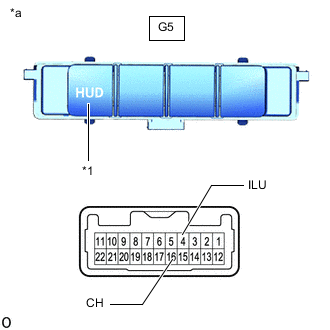
*1 HUD Switch *a Component without harness connected
(Headup Display Switch (Integration Control and Panel Assembly)
Check the resistance.
-
Measure the resistance according to the value(s) in the table below.
Standard Resistance Tester Connection Switch Condition Specified Condition G5-4 (ILU) - G5-16 (CH) HUD switch not pressed 10 kΩ or higher HUD switch pressed Below 1 Ω If the result is not as specified, replace the headup display switch (integration control and panel assembly).
-
-
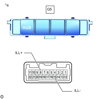
*a Component without harness connected
(Headup Display Switch (Integration Control and Panel Assembly)
Check illumination.
-
Apply auxiliary battery voltage to the connector and check the light illumination condition.
OK Tester Connection Specified Condition G5-8 (ILL+) - Auxiliary battery positive (+)
G5-15 (ILL-) - Auxiliary battery negative (-)
Illuminates If the result is not as specified, replace the headup display switch (integration control and panel assembly).
-
-
Install the headup display switch (integration control and panel assembly).
-
- Click here
INSPECT HEADUP DISPLAY SWITCH (INTEGRATION CONTROL AND PANEL ASSEMBLY) (for RHD)
-
Remove the headup display switch (integration control and panel assembly).
-
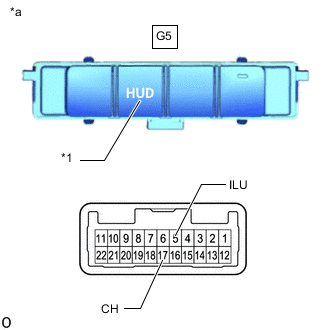
*1 HUD Switch *a Component without harness connected
(Headup Display Switch (Integration Control and Panel Assembly)
Check the resistance.
-
Measure the resistance according to the value(s) in the table below.
Standard Resistance Tester Connection Switch Condition Specified Condition G5-5 (ILU) - G5-17 (CH) HUD switch not pressed 10 kΩ or higher HUD switch pressed Below 1 Ω If the result is not as specified, replace the headup display switch (integration control and panel assembly).
-
-
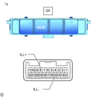
*a Component without harness connected
(Headup Display Switch (Integration Control and Panel Assembly)
Check illumination.
-
Apply auxiliary battery voltage to the connector and check the light illumination condition.
OK Tester Connection Specified Condition G5-8 (ILL+) - Auxiliary battery positive (+)
G5-15 (ILL-) - Auxiliary battery negative (-)
Illuminates If the result is not as specified, replace the headup display switch (integration control and panel assembly).
-
-
Install the headup display switch (integration control and panel assembly).
-