Click here
-
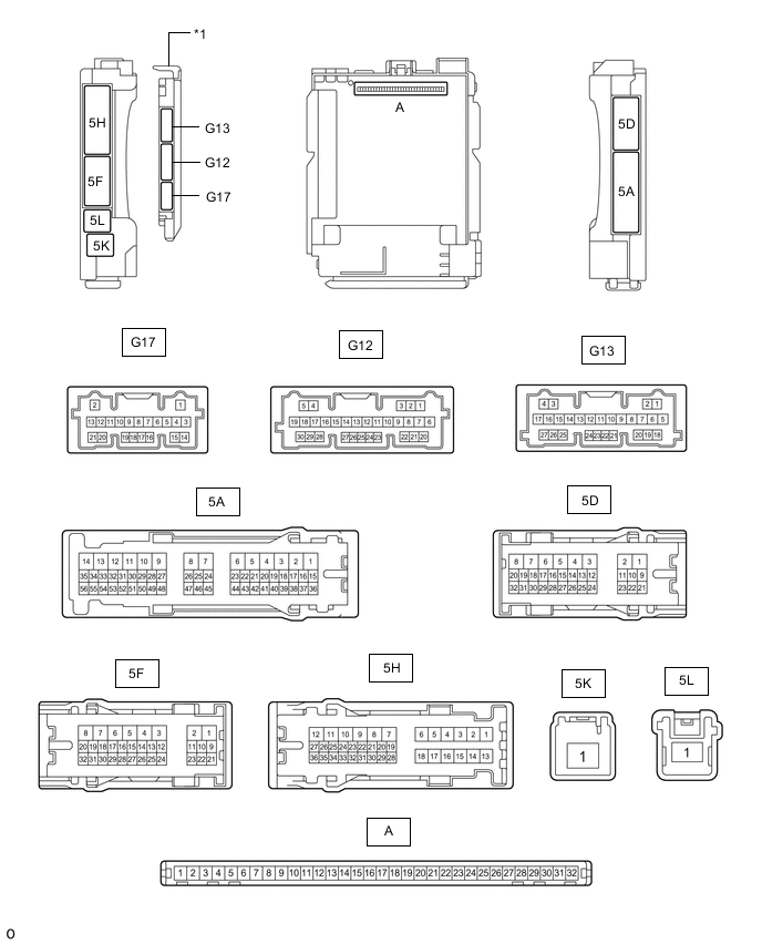
*1 Main Body ECU (Multiplex Network Body ECU) - - CHECK INSTRUMENT PANEL JUNCTION BLOCK ASSEMBLY AND MAIN BODY ECU (MULTIPLEX NETWORK BODY ECU)
-
Remove the main body ECU (multiplex network body ECU) from the instrument panel junction block assembly.
-
Connect the instrument panel junction block assembly connectors.
-
Measure the voltage and resistance according to the value(s) in the table below.
Terminal No. (Symbol) Wiring Color Terminal Description Condition Specified Condition A-32 (IG) - Body ground None - Body ground Ignition power supply Power switch on (IG) 11 to 14 V Power switch off Below 1 V A-31 (BECU) - Body ground None - Body ground Auxiliary battery power supply Power switch off 11 to 14 V A-30 (ACC) - Body ground None - Body ground ACC power supply Power switch on (ACC) 11 to 14 V Power switch off Below 1 V A-11 (GND1) - Body ground None - Body ground Ground Always Below 1 Ω -
Install the main body ECU (multiplex network body ECU).
-
Measure the voltage and pulse according to the value(s) in the table below.
Terminal No. (Symbol) Wiring Color Terminal Description Condition Specified Condition G17-21 (LED2) - Body ground LG - Body ground Multi-display (interior illumination light assembly) output Multi-display (interior illumination light assembly) off 11 to 14 V Multi-display (interior illumination light assembly) on Below 1 V G12-1 (FLCY) - Body ground R - Body ground Front door courtesy light switch assembly LH input Front door LH open Below 1 V Front door LH closed 4.7 to 5.3 V G12-6 (FRCY) - Body ground SB - Body ground*1
R - Body ground*2
Front door courtesy light switch assembly RH input Front door RH open Below 1 V Front door RH closed 4.7 to 5.3 V 5H-26 (LCTY) - Body ground*1 G - Body ground Rear door courtesy light switch assembly LH input Rear door LH open Below 1 V Rear door LH closed 4.7 to 5.3 V 5A-42 (LCTY) - Body ground*2 G - Body ground Rear door courtesy light switch assembly LH input Rear door LH open Below 1 V Rear door LH closed 4.7 to 5.3 V 5D-19 (RCTY) - Body ground*1 R - Body ground Rear door courtesy light switch assembly RH input Rear door RH open Below 1 V Rear door RH closed 4.7 to 5.3 V 5H-26 (RCTY) - Body ground*2 R - Body ground Rear door courtesy light switch assembly RH input Rear door RH open Below 1 V Rear door RH closed 4.7 to 5.3 V G12-2 (FLCL) - Body ground V - Body ground Courtesy light assembly (for Front LH Side) output Courtesy light assembly (for front LH side) on Below 1 V Courtesy light assembly (for front LH side) off 11 to 14 V G12-3 (FRCL) - Body ground G - Body ground Courtesy light assembly (for Front RH Side) output Courtesy light assembly (for front RH side) on Below 1 V Courtesy light assembly (for front RH side) off 11 to 14 V G13-5 (LCYL) - Body ground L - Body ground Courtesy light assembly (for Rear LH Side) output Courtesy light assembly (for rear LH side) on Below 1 V Courtesy light assembly (for rear LH side) off 11 to 14 V G13-18 (RCYL) - Body ground LG - Body ground Courtesy light assembly (for Rear RH Side) output Courtesy light assembly (for rear RH side) on Below 1 V Courtesy light assembly (for rear RH side) off 11 to 14 V 5H-31 (LSFL) - Body ground*1 P - Body ground Front door LH unlock detection switch input Front door LH locked Pulse generation Front door LH unlocked Below 1 V 5A-15 (LSFL) - Body ground*2 B - Body ground Front door LH unlock detection switch input Front door LH locked Pulse generation Front door LH unlocked Below 1 V 5D-14 (LSFR) - Body ground*1 GR - Body ground Front door RH unlock detection switch input Front door RH locked Pulse generation Front door LH unlocked Below 1 V 5H-31 (LSFR) - Body ground*2 GR - Body ground Front door RH unlock detection switch input Front door RH locked Pulse generation Front door LH unlocked Below 1 V 5H-21 (LSWL) - Body ground*1 SB - Body ground Rear door LH unlock detection switch input Rear door LH locked Pulse generation Rear door LH unlocked Below 1 V 5D-12 (LSWL) - Body ground*2 B - Body ground Rear door LH unlock detection switch input Rear door LH locked Pulse generation Rear door LH unlocked Below 1 V G13-20 (LSWR) - Body ground B - Body ground Rear door RH unlock detection switch input Rear door RH locked Pulse generation Rear door LH locked Below 1 V 5A-36 (FSPT) - Body ground SB - Body ground No. 1 interior illumination light assembly (footwell light) output No. 1 interior illumination light assembly (footwell light) off 11 to 14 V No. 1 interior illumination light assembly (footwell light) on Below 1 V 5A-37 (FSPT) - Body ground GR - Body ground No. 2 interior illumination light assembly (footwell light) output No. 2 interior illumination light assembly (footwell light) off 11 to 14 V No. 2 interior illumination light assembly (footwell light) on Below 1 V 5H-30 (FSPT) - Body ground R - Body ground No. 3 interior illumination light assembly (footwell light) output No. 3 interior illumination light assembly (footwell light) off 11 to 14 V No. 3 interior illumination light assembly (footwell light) on Below 1 V G12-10 (BLIL) - Body ground*3 W - Body ground Rear seat belt buckle illumination light output Rear seat belt buckle illumination light off 11 to 14 V Rear seat belt buckle illumination light on Below 1 V 5D-5 - Body ground LA-G - Body ground Map light sub-assembly power supply DOME CUT D relay off 11 to 14 V DOME CUT D relay on Below 1 V G12-8 (ACAN) - Body ground Y - Body ground Dimming signal for other system (Output) Power switch on (IG), automatic light control sensor not covered by hand, and light control switch in AUTO position 11 to 14 V Power switch on (IG), automatic light control sensor covered by hand, and light control switch in AUTO position Below 1 V 5A-16 - Body ground*2 LA-G - Body ground Power switch on (IG), light control switch off Power switch on (IG), light control switch TAIL 11 to 14 V Power switch on (IG), light control switch off Below 1 V 5A-17 - Body ground*2 LA-L - Body ground Power switch on (IG), light control switch off Power switch on (IG), light control switch TAIL 11 to 14 V Power switch on (IG), light control switch off Below 1 V 5A-39 - Body ground*1 LA-G - Body ground Taillight signal Power switch on (IG), light control switch TAIL 11 to 14 V Power switch on (IG), light control switch off Below 1 V 5A-40 - Body ground*1 LA-L - Body ground Taillight signal Power switch on (IG), light control switch TAIL 11 to 14 V Power switch on (IG), light control switch off Below 1 V 5H-20 - Body ground LA-G - Body ground Taillight signal Power switch on (IG), light control switch TAIL 11 to 14 V Power switch on (IG), light control switch off Below 1 V *1: for LHD
*2: for RHD
*3: w/o Rear Power Seat System
-
-
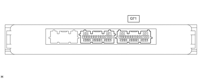
CHECK CERTIFICATION ECU (SMART KEY ECU ASSEMBLY)
-
Disconnect the G71 certification ECU (smart key ECU assembly) connector.
-
Measure the voltage and resistance according to the value(s) in the table below.
Terminal No. (Symbol) Wiring Color Terminal Description Condition Specified Condition G71-4 (+B) - Body ground W - Body ground Auxiliary battery power supply Power switch off 11 to 14 V G71-15 (CUTB)- Body ground P - Body ground Auxiliary battery power supply Power switch off 11 to 14 V G71-18 (E) - Body ground W-B - Body ground Ground Always Below 1 Ω -
Reconnect the G71 certification ECU (smart key ECU assembly) connector.
-
Measure the voltage according to the value(s) in the table below.
Terminal No. (Symbol) Wiring Color Terminal Description Condition Specified Condition G71-10 (SWIL) - G71-11 (AGND) P - L Power switch illumination drive output Power switch illumination on 11 to 14 V Power switch illumination off Below 1 V
-
-

FRONT MULTIPLEX NETWORK DOOR ECU LH
-
Disconnect the H31 front multiplex network door ECU LH connector.
-
Measure the voltage and resistance according to the value(s) in the table below.
Terminal No. (Symbol) Wiring Color Terminal Description Condition Specified Condition H31-4 (CPUB) - Body ground L - Body ground Auxiliary battery power supply Power switch off 11 to 14 V H31-6 (BDR) - Body ground R - Body ground Auxiliary battery power supply Power switch off 11 to 14 V H31-3 (SIG) - Body ground B - Body ground Ignition power supply Power switch on (IG) 11 to 14 V Power switch off Below 1 V H31-1 (GND) - Body ground W-B - Body ground Ground Always Below 1 Ω -
Reconnect the H31 front multiplex network door ECU LH connector.
-
Measure the voltage according to the value(s) in the table below.
Terminal No. (Symbol) Wiring Color Terminal Description Condition Specified Condition H31-14 (ILL+) - Body ground G - Body ground Auxiliary battery power supply Power switch off 11 to 14 V H29-7 (LED+) - H29-20 (LED-) R - L Front door trim board sub-assembly LH (armrest illumination) output Front door trim board sub-assembly LH (armrest illumination) off Below 1 V Front door trim board sub-assembly LH (armrest illumination) on 11 to 14 V H29-21 (IL1+) - H29-19 (IL1-) W - L Front door trim board sub-assembly LH (ornament illumination) output Front door trim board sub-assembly LH (ornament illumination) off Below 1 V Front door trim board sub-assembly LH (ornament illumination) on 11 to 14 V H29-15 (IL2-) - Body ground B - Body ground Front door trim board sub-assembly LH (front door inside handle illumination) output Front door trim board sub-assembly LH (front door inside handle illumination) off 11 to 14 V Front door trim board sub-assembly LH (front door inside handle illumination) on Below 1 V
-
-

FRONT MULTIPLEX NETWORK DOOR ECU RH
-
Disconnect the H12 front multiplex network door ECU RH connector.
-
Measure the voltage and resistance according to the value(s) in the table below.
Terminal No. (Symbol) Wiring Color Terminal Description Condition Specified Condition H12-4 (CPUB) - Body ground L - Body ground Auxiliary battery power supply Power switch off 11 to 14 V H12-6 (BDR) - Body ground R - Body ground Auxiliary battery power supply Power switch off 11 to 14 V H12-3 (SIG) - Body ground B - Body ground Ignition power supply Power switch on (IG) 11 to 14 V Power switch off Below 1 V H12-1 (GND) - Body ground W-B - Body ground Ground Always Below 1 Ω -
Reconnect the H12 front multiplex network door ECU RH connector.
-
Measure the voltage according to the value(s) in the table below.
Terminal No. (Symbol) Wiring Color Terminal Description Condition Specified Condition H12-14 (ILL+) - Body ground L - Body ground Auxiliary battery power supply Power switch off 11 to 14 V H10-7 (LED+) - H10-20 (LED-) R - L Front door trim board sub-assembly RH (armrest illumination) output Front door trim board sub-assembly RH (armrest illumination) off Below 1 V Front door trim board sub-assembly RH (armrest illumination) on 11 to 14 V H10-21 (IL1+) - H10-19 (IL1-) LG - L Front door trim board sub-assembly RH (ornament illumination) output Front door trim board sub-assembly RH (ornament illumination) off Below 1 V Front door trim board sub-assembly RH (ornament illumination) on 11 to 14 V H10-15 (IL2-) - Body ground B - Body ground Front door trim board sub-assembly RH (front door inside handle illumination) output Front door trim board sub-assembly RH (front door inside handle illumination) off 11 to 14 V Front door trim board sub-assembly RH (front door inside handle illumination) on Below 1 V
-
-

REAR MULTIPLEX NETWORK DOOR ECU LH
-
Disconnect the K21 rear multiplex network door ECU LH connector.
-
Measure the voltage and resistance according to the value(s) in the table below.
Terminal No. (Symbol) Wiring Color Terminal Description Condition Specified Condition K21-11 (CPUB) - Body ground L - Body ground Auxiliary battery power supply Power switch off 11 to 14 V K21-4 (BDR) - Body ground L - Body ground Auxiliary battery power supply Power switch off 11 to 14 V K21-12 (SIG) - Body ground B - Body ground Ignition power supply Power switch on (IG) 11 to 14 V Power switch off Below 1 V K21-1 (GND) - Body ground LA - Body ground Ground Always Below 1 Ω -
Reconnect the K21 rear multiplex network door ECU LH connector.
-
Measure the voltage according to the value(s) in the table below.
Terminal No. (Symbol) Wiring Color Terminal Description Condition Specified Condition K21-14 (ILL+) - Body ground GR - Body ground Auxiliary battery power supply Power switch off 11 to 14 V K20-7 (LED+) - K20-20 (LED-) LG - BE Rear door trim board sub-assembly LH (armrest illumination) output Rear door trim board sub-assembly LH (armrest illumination) off Below 1 V Rear door trim board sub-assembly LH (armrest illumination) on 11 to 14 V K20-18 (ASH+) - K20-3 (ASH-) P - GR Rear door trim board sub-assembly LH (ornament illumination) output Rear door trim board sub-assembly LH (ornament illumination) off Below 1 V Rear door trim board sub-assembly LH (ornament illumination) on 11 to 14 V K20-21 (IL2-) - Body ground B - Body ground Rear door trim board sub-assembly LH (rear door inside handle illumination) output Rear door trim board sub-assembly LH (rear door inside handle illumination) off 11 to 14 V Rear door trim board sub-assembly LH (rear door inside handle illumination) on Below 1 V
-
-

REAR MULTIPLEX NETWORK DOOR ECU RH
-
Disconnect the K7 rear multiplex network door ECU RH connector.
-
Measure the voltage and resistance according to the value(s) in the table below.
Terminal No. (Symbol) Wiring Color Terminal Description Condition Specified Condition K7-11 (CPUB) - Body ground L - Body ground Auxiliary battery power supply Power switch off 11 to 14 V K7-4 (BDR) - Body ground B - Body ground Auxiliary battery power supply Power switch off 11 to 14 V K7-12 (SIG) - Body ground L - Body ground Ignition power supply Power switch on (IG) 11 to 14 V Power switch off Below 1 V K7-1 (GND) - Body ground LA - Body ground Ground Always Below 1 Ω -
Reconnect the K7 rear multiplex network door ECU RH connector.
-
Measure the voltage according to the value(s) in the table below.
Terminal No. (Symbol) Wiring Color Terminal Description Condition Specified Condition K7-14 (ILL+) - Body ground R - Body ground Auxiliary battery power supply Power switch off 11 to 14 V K6-7 (LED+) - K6-20 (LED-) SB - BE Rear door trim board sub-assembly RH (armrest illumination) output Rear door trim board sub-assembly RH (armrest illumination) off Below 1 V Rear door trim board sub-assembly RH (armrest illumination) on 11 to 14 V K6-18 (ASH+) - K6-3 (ASH-) LG - L Rear door trim board sub-assembly RH (ornament illumination) output Rear door trim board sub-assembly RH (ornament illumination) off Below 1 V Rear door trim board sub-assembly RH (ornament illumination) on 11 to 14 V K6-21 (IL2-) - Body ground B - Body ground Rear door trim board sub-assembly RH (rear door inside handle illumination) output Rear door trim board sub-assembly RH (rear door inside handle illumination) off 11 to 14 V Rear door trim board sub-assembly RH (rear door inside handle illumination) on Below 1 V
-
-
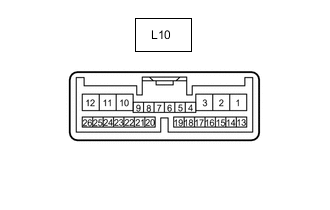
LUGGAGE CLOSER MOTOR ASSEMBLY
-
Disconnect the L10 luggage closer motor assembly connector.
-
Measure the voltage and resistance according to the value(s) in the table below.
Terminal No. (Symbol) Wiring Color Terminal Description Condition Specified Condition L10-10 (ECUB) - Body ground LA-L - Body ground Auxiliary battery power supply Power switch off 11 to 14 V L10-12 (B) - Body ground B - Body ground Auxiliary battery power supply Power switch off 11 to 14 V L10-8 (IG) - Body ground B - Body ground Ignition power supply Power switch on (IG) 11 to 14 V Power switch off Below 1 V L10-11 (GND) - Body ground W-B - Body ground Ground Always Below 1 Ω -
Reconnect the L10 luggage closer motor assembly connector.
-
Measure the voltage according to the value(s) in the table below.
Terminal No. (Symbol) Wiring Color Terminal Description Condition Specified Condition L10-3 (ILL) - Body ground B - Body ground Luggage compartment light output Luggage compartment door open Below 1 V Luggage compartment door closed 11 to 14 V
-
-
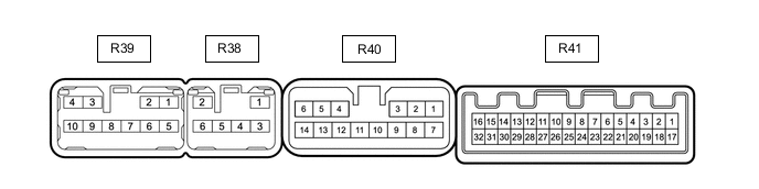
POSITION CONTROL ECU ASSEMBLY LH
-
Disconnect the R40 and R41 position control ECU assembly LH connectors.
-
Measure the voltage and resistance according to the value(s) in the table below.
Terminal No. (Symbol) Wiring Color Terminal Description Condition Specified Condition R40-14 (+B1) - Body ground W - Body ground Auxiliary battery power supply Power switch off 11 to 14 V R40-13 (+B2) - Body ground W - Body ground Auxiliary battery power supply Power switch off 11 to 14 V R40-12 (+B3) - Body ground W - Body ground Auxiliary battery power supply Power switch off 11 to 14 V R41-15 (IG) - Body ground LG - Body ground Ignition power supply Power switch on (IG) 11 to 14 V Power switch off Below 1 V R40-8 (GND2) - Body ground W-B - Body ground Ground Always Below 1 Ω R40-9 (GND1) - Body ground W-B - Body ground Ground Always Below 1 Ω -
Reconnect the R40 and R41 position control ECU assembly LH connectors.
-
Measure the voltage according to the value(s) in the table below.
Terminal No. (Symbol) Wiring Color Terminal Description Condition Specified Condition R41-32 (BCLL) - Body ground L - Body ground Rear seat buckle illumination light LH output Rear seat buckle illumination light LH off Below 1 V Rear seat buckle illumination light LH on 11 to 14 V
-
-
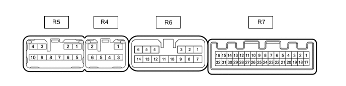
POSITION CONTROL ECU ASSEMBLY RH
-
Disconnect the R6 and R7 position control ECU assembly RH connectors.
-
Measure the voltage and resistance according to the value(s) in the table below.
Terminal No. (Symbol) Wiring Color Terminal Description Condition Specified Condition R6-14 (+B1) - Body ground W - Body ground Auxiliary battery power supply Power switch off 11 to 14 V R6-13 (+B2) - Body ground W - Body ground Auxiliary battery power supply Power switch off 11 to 14 V R6-12 (+B3) - Body ground W - Body ground Auxiliary battery power supply Power switch off 11 to 14 V R7-15 (IG) - Body ground LG - Body ground Ignition power supply Power switch on (IG) 11 to 14 V Power switch off Below 1 V R6-8 (GND2) - Body ground W-B - Body ground Ground Always Below 1 Ω R6-9 (GND1) - Body ground W-B - Body ground Ground Always Below 1 Ω -
Reconnect the R6 and R7 position control ECU assembly RH connectors.
-
Measure the voltage according to the value(s) in the table below.
Terminal No. (Symbol) Wiring Color Terminal Description Condition Specified Condition R7-32 (BCLL) - Body ground L - Body ground Rear seat buckle illumination light LH output Rear seat buckle illumination light RH off Below 1 V Rear seat buckle illumination light RH on 11 to 14 V
-