| DTC Code | DTC Name |
|---|---|
| Door Unlock Detection Switch Circuit |
DESCRIPTION
The main body ECU (multiplex network body ECU) detects the condition of each door unlock detection switch.
CAUTION / NOTICE / HINT
Before replacing the main body ECU (multiplex network body ECU), refer to Service Bulletin.
PROCEDURE
- Click here
READ VALUE USING GTS
-
Read the Data List according to the display on the GTS.
- Body Electrical > Main Body > Data List
Tester Display Measurement Item Range Normal Condition Diagnostic Note FR Door Lock Pos Front door RH unlock detection switch signal UNLOCK or LOCK UNLOCK: Front door RH unlocked
LOCK: Front door RH locked
- FL Door Lock Pos Front door LH unlock detection switch signal UNLOCK or LOCK UNLOCK: Front door LH unlocked
LOCK: Front door LH locked
- RR-Door Lock Pos SW Rear door RH unlock detection switch signal OFF or ON OFF: Rear door RH unlocked
ON: Rear door RH locked
- RL-Door Lock Pos SW Rear door LH unlock detection switch signal OFF or ON OFF: Rear door LH unlocked
ON: Rear door LH locked
- -
-
- Body Electrical > Main Body > Data List
Tester Display FR Door Lock Pos FL Door Lock Pos RR-Door Lock Pos SW RL-Door Lock Pos SW -
-
-
-
OK Normal conditions listed above are displayed. Result Result Proceed to OK A NG ("FR Door Lock Pos" is abnormal) B NG ("FL Door Lock Pos" is abnormal) C NG ("RR-Door Lock Pos SW" is abnormal) D NG ("RL-Door Lock Pos SW" is abnormal) E - Body Electrical > Main Body > Data List
- A
PROCEED TO NEXT SUSPECTED AREA SHOWN IN PROBLEM SYMPTOMS TABLEClick here
- BClick here
- CClick here
- DClick here
- EClick here
-
- Click here
INSPECT FRONT DOOR WITH MOTOR LOCK ASSEMBLY RH
-
Remove the front door with motor lock assembly RH.
-
Inspect the front door with motor lock assembly RH.
Result Proceed to OK NG
- OKClick here
- NG
REPLACE FRONT DOOR WITH MOTOR LOCK ASSEMBLY RHClick here
-
- Click here
CHECK HARNESS AND CONNECTOR (FRONT DOOR WITH MOTOR LOCK ASSEMBLY RH - INSTRUMENT PANEL JUNCTION BLOCK ASSEMBLY)
-
Disconnect the H6 front door with motor lock assembly RH connector.
-
Disconnect the 5D*1 or 5H*2 instrument panel junction block assembly connector.
-
*1: for LHD
-
*2: for RHD
-
-
Measure the resistance according to the value(s) in the table below.
Standard Resistance Table 1. for LHD Tester Connection Condition Specified Condition H6-5 (LSSR) - 5D-14 Always Below 1 Ω H6-6 (E) - Body ground Always Below 1 Ω H6-5 (LSSR) or 5D-14 - Body ground Always 10 kΩ or higher Table 2. for RHD Tester Connection Condition Specified Condition H6-5 (LSSR) - 5H-31 Always Below 1 Ω H6-6 (E) - Body ground Always Below 1 Ω H6-5 (LSSR) or 5H-31 - Body ground Always 10 kΩ or higher Result Proceed to OK NG
- OKClick here
- NG
REPAIR OR REPLACE HARNESS OR CONNECTOR
-
- Click here
CHECK INSTRUMENT PANEL JUNCTION BLOCK ASSEMBLY
-
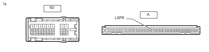
*a Component without harness connected
(Instrument Panel Junction Block Assembly)
- - for LHD:
-
Remove the instrument panel junction block assembly.
-
Remove the main body ECU (multiplex network body ECU) from the instrument panel junction block assembly.
-
Measure the resistance according to the value(s) in the table below.
Standard Resistance Tester Connection Condition Specified Condition 5D-14 - A-17 (LSFR) Always Below 1 Ω
-
-
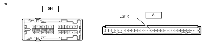
*a Component without harness connected
(Instrument Panel Junction Block Assembly)
- - for RHD:
-
Remove the instrument panel junction block assembly.
-
Remove the main body ECU (multiplex network body ECU) from the instrument panel junction block assembly.
-
Measure the resistance according to the value(s) in the table below.
Standard Resistance Tester Connection Condition Specified Condition 5H-31 - A-17 (LSFR) Always Below 1 Ω
Result Proceed to OK NG -
- OK
REPLACE MAIN BODY ECU (MULTIPLEX NETWORK BODY ECU)Click here
- NG
REPLACE INSTRUMENT PANEL JUNCTION BLOCK ASSEMBLY Click here
REPLACE INSTRUMENT PANEL JUNCTION BLOCK ASSEMBLYClick here
-
- Click here
INSPECT FRONT DOOR WITH MOTOR LOCK ASSEMBLY LH
-
Remove the front door with motor lock assembly LH.
-
Inspect the front door with motor lock assembly LH.
Result Proceed to OK NG
- OKClick here
- NG
REPLACE FRONT DOOR WITH MOTOR LOCK ASSEMBLY LHClick here
-
- Click here
CHECK HARNESS AND CONNECTOR (FRONT DOOR WITH MOTOR LOCK ASSEMBLY LH - INSTRUMENT PANEL JUNCTION BLOCK ASSEMBLY)
-
Disconnect the H23 front door with motor lock assembly LH connector.
-
Disconnect the 5H*1 or 5A*2 instrument panel junction block assembly connector.
-
*1: for LHD
-
*2: for RHD
-
-
Measure the resistance according to the value(s) in the table below.
Standard Resistance Table 3. for LHD Tester Connection Condition Specified Condition H23-10 (LSSR) - 5H-31 Always Below 1 Ω H23-9 (E) - Body ground Always Below 1 Ω H23-10 (LSSR) or 5H-31 - Body ground Always 10 kΩ or higher Table 4. for RHD Tester Connection Condition Specified Condition H23-10 (LSSR) - 5A-15 Always Below 1 Ω H23-9 (E) - Body ground Always Below 1 Ω H23-10 (LSSR) or 5A-15 - Body ground Always 10 kΩ or higher Result Proceed to OK NG
- OKClick here
- NG
REPAIR OR REPLACE HARNESS OR CONNECTOR
-
- Click here
CHECK INSTRUMENT PANEL JUNCTION BLOCK ASSEMBLY
-
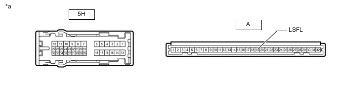
*a Component without harness connected
(Instrument Panel Junction Block Assembly)
- - for LHD:
-
Remove the instrument panel junction block assembly.
-
Remove the main body ECU (multiplex network body ECU) from the instrument panel junction block assembly.
-
Measure the resistance according to the value(s) in the table below.
Standard Resistance Tester Connection Condition Specified Condition 5H-31 - A-19 (LSFL) Always Below 1 Ω
-
-
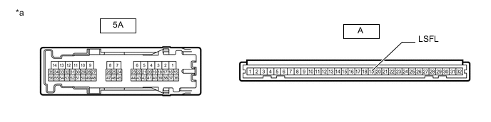
*a Component without harness connected
(Instrument Panel Junction Block Assembly)
- - for RHD:
-
Remove the instrument panel junction block assembly.
-
Remove the main body ECU (multiplex network body ECU) from the instrument panel junction block assembly.
-
Measure the resistance according to the value(s) in the table below.
Standard Resistance Tester Connection Condition Specified Condition 5A-15 - A-19 (LSFL) Always Below 1 Ω
Result Proceed to OK NG -
- OK
REPLACE MAIN BODY ECU (MULTIPLEX NETWORK BODY ECU)Click here
- NG
REPLACE INSTRUMENT PANEL JUNCTION BLOCK ASSEMBLY Click here
REPLACE INSTRUMENT PANEL JUNCTION BLOCK ASSEMBLYClick here
-
- Click here
INSPECT REAR DOOR LOCK ASSEMBLY RH
-
Remove the rear door lock assembly RH.
-
Inspect the rear door lock assembly RH.
Result Proceed to OK NG
- OKClick here
- NG
REPLACE REAR DOOR LOCK ASSEMBLY RHClick here
-
- Click here
CHECK HARNESS AND CONNECTOR (REAR DOOR LOCK ASSEMBLY RH - MAIN BODY ECU [MULTIPLEX NETWORK BODY ECU])
-
Disconnect the K2 rear door lock assembly RH connector.
-
Disconnect the G13 main body ECU (multiplex network body ECU) connector.
-
Measure the resistance according to the value(s) in the table below.
Standard Resistance Tester Connection Condition Specified Condition K2-5 (LSSR) - G13-20 (LSWR) Always Below 1 Ω K2-6 (E) - Body ground Always Below 1 Ω K2-5 (LSSR) or G13-20 (LSWR) - Body ground Always 10 kΩ or higher Result Proceed to OK NG
- OK
REPLACE MAIN BODY ECU (MULTIPLEX NETWORK BODY ECU)Click here
- NG
REPAIR OR REPLACE HARNESS OR CONNECTOR
-
- Click here
INSPECT REAR DOOR LOCK ASSEMBLY LH
-
Remove the rear door lock assembly LH.
-
Inspect the rear door lock assembly LH.
Result Proceed to OK NG
- OKClick here
- NG
REPLACE REAR DOOR LOCK ASSEMBLY LHClick here
-
- Click here
CHECK HARNESS AND CONNECTOR (REAR DOOR LOCK ASSEMBLY LH - INSTRUMENT PANEL JUNCTION BLOCK ASSEMBLY)
-
Disconnect the K16 rear door lock assembly LH connector.
-
Disconnect the 5H*1 or 5D*2 instrument panel junction block assembly connector.
-
*1: for LHD
-
*2: for RHD
-
-
Measure the resistance according to the value(s) in the table below.
Standard Resistance Table 5. for LHD Tester Connection Condition Specified Condition K16-9 (LSSR) - 5H-21 Always Below 1 Ω K16-10 (E) - Body ground Always Below 1 Ω K16-9 (LSSR) or 5H-21 - Body ground Always 10 kΩ or higher Table 6. for RHD Tester Connection Condition Specified Condition K16-9 (LSSR) - 5D-12 Always Below 1 Ω K16-10 (E) - Body ground Always Below 1 Ω K16-9 (LSSR) or 5D-12 - Body ground Always 10 kΩ or higher Result Proceed to OK NG
- OKClick here
- NG
REPAIR OR REPLACE HARNESS OR CONNECTOR
-
- Click here
CHECK INSTRUMENT PANEL JUNCTION BLOCK ASSEMBLY
-
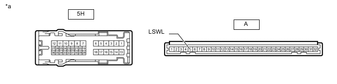
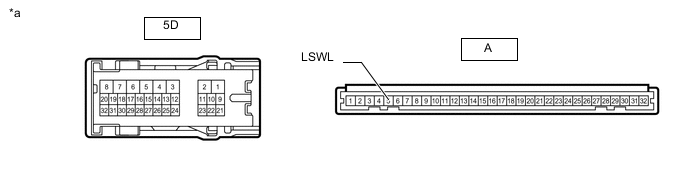
*a Component without harness connected
(Instrument Panel Junction Block Assembly)
- - for LHD:
-
Remove the instrument panel junction block assembly.
-
Remove the main body ECU (multiplex network body ECU) from the instrument panel junction block assembly.
-
Measure the resistance according to the value(s) in the table below.
Standard Resistance Tester Connection Condition Specified Condition 5H-21 - A-5 (LSWL) Always Below 1 Ω
-
-
*a Component without harness connected
(Instrument Panel Junction Block Assembly)
- - for RHD:
-
Remove the instrument panel junction block assembly.
-
Remove the main body ECU (multiplex network body ECU) from the instrument panel junction block assembly.
-
Measure the resistance according to the value(s) in the table below.
Standard Resistance Tester Connection Condition Specified Condition 5D-12 - A-5 (LSWL) Always Below 1 Ω
Result Proceed to OK NG -
- OK
REPLACE MAIN BODY ECU (MULTIPLEX NETWORK BODY ECU)Click here
- NG
REPLACE INSTRUMENT PANEL JUNCTION BLOCK ASSEMBLYClick here
-