ENTRY AND START SYSTEM(for Start Function), Diagnostic DTC:B2285
| DTC Code | DTC Name |
|---|---|
| B2285 | Steering Lock Position Signal Circuit Malfunction |
DESCRIPTION
This DTC is stored when the steering lock position signal sent by the steering lock ECU (steering lock actuator or upper bracket assembly) via direct line and the steering lock position signal sent via LIN communication do not match.
| DTC No. | Detection Item | DTC Detection Condition | Trouble Area | Note |
|---|---|---|---|---|
| B2285 | Steering Lock Position Signal Circuit Malfunction | The steering lock position signal sent by the steering lock ECU (steering lock actuator or upper bracket assembly) via direct line and the steering lock position signal sent via LIN communication do not match. (1-trip detection logic*1) |
|
DTC Output Confirmation Operation: |
-
*1: Only detected while a malfunction is present.
-
*2: for LEXUS Enform Remote Compatible Type
| Vehicle Condition when Malfunction Detected | Fail-safe Function when Malfunction Detected |
|---|---|
| The hybrid control system cannot be started. | The ECU does not send a hybrid control system start request. |
| DTC No. | Data List and Active Test |
|---|---|
| B2285 |
Power Source Control
Entry&Start |
WIRING DIAGRAM
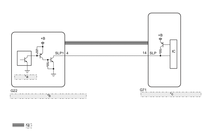
| *a | Unlock Sensor |
| *b | Steering Lock ECU (Steering Lock Actuator or Upper Bracket Assembly) |
| *c | Certification ECU (Smart Key ECU Assembly) |
| *d | LIN Communication Line |
CAUTION / NOTICE / HINT
Note
-
When using the GTS with the power switch off, connect the GTS to the DLC3 and turn a courtesy light switch on and off at intervals of 1.5 seconds or less until communication between the GTS and the vehicle begins. Then select Model Code "KEY REGIST" under manual mode and enter the following menus: Body Electrical / Entry&Start. While using the GTS, periodically turn a courtesy light switch on and off at intervals of 1.5 seconds or less to maintain communication between the GTS and the vehicle.
-
The entry and start system (for Start Function) uses the LIN communication system and CAN communication system. Inspect the communication function by following How to Proceed with Troubleshooting. Troubleshoot the entry and start system (for Start Function) after confirming that the communication systems are functioning properly.
-
Before replacing the certification ECU (smart key ECU assembly), steering lock ECU (steering lock actuator or upper bracket assembly) or telephone transceiver assembly*, refer to the Service Bulletin.
-
After repair, confirm that no DTCs are output by performing "DTC Output Confirmation Operation".
-
*: for LEXUS ENFORM Remote Compatible Type
PROCEDURE
-
CHECK FOR DTC
-
Connect the GTS to the DLC3.
-
Turn the power switch on (IG).
-
Turn the GTS on.
-
Enter the following menus: Body Electrical / Entry&Start / Trouble Codes.
-
Check for DTCs.
Body Electrical > Entry&Start > Trouble CodesTech Tips
-
If the steering cannot be unlocked, the power switch cannot be turned on (IG) and the hybrid control system cannot be started.
-
If LIN communication is not available, the steering cannot be locked or unlocked.
Result Result Proceed to DTC B2785 is not output. A DTC B2785 is output. B -
B 
GO TO DTC B2785 Click here
A 
-
-
READ VALUE USING GTS (STEERING UNLOCK SWITCH)
-
Enter the following menus: Body Electrical / Power Source Control / Data List.
-
Read the Data List according to the display on the GTS.
Body Electrical > Power Source Control > Data ListTester Display Measurement Item Range Normal Condition Diagnostic Note Steering Unlock Switch State of steering unlock sensor signal output from steering lock ECU (steering lock actuator or upper bracket assembly) OFF or ON OFF: Steering locked
ON: Steering unlocked
-
When the shift state is in part (P) and the power switch is off, if any door is opened or closed, the steering is locked.
-
When the electrical key transmitter sub-assembly is in the cabin and the power switch is turned on (ACC) or on (IG), the steering unlocks.
-
The hybrid control system cannot be started when the steering unlock signal is off.
Body Electrical > Power Source Control > Data ListTester Display Steering Unlock Switch OK The GTS display changes correctly in response to the steering lock/unlock status. Result Result Proceed to GTS display does not change A GTS display changes B -
B
REPLACE STEERING LOCK ECU (STEERING LOCK ACTUATOR OR UPR BRACKET ASSEMBLY) Click here
A
-
-
CHECK STEERING LOCK ECU (STEERING LOCK ACTUATOR OR UPR BRACKET ASSEMBLY)
-
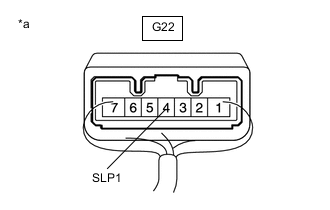
*a Component with harness connected
(Steering Lock ECU (Steering Lock Actuator or Upper Bracket Assembly))
Measure the voltage according to the value(s) inthe table below.
Standard Voltage Tester Connection Condition Specified Condition G22-4 (SLP1) -Body ground Steering locked →unlocked* 11 to 14 V→Below 1.5 V Tech Tips
-
*: If any of the doors are opened with theshift state park (P) and the power switchoff, the steering will be locked. If the powerswitch is turned on (ACC) or on (IG) withthe electrical key transmitter sub-assemblyin the cabin, the steering will be unlocked.
-
DTC B2285 may be stored due to amalfunction in the steering lock ECU(steering lock actuator or upper bracket assembly). The steering lock position signaland unlock position signal are sent from the steering lock ECU (steering lock actuator orupper bracket assembly) to the certification ECU (smart key ECU assembly) individually.
Result Proceed to OK NG -
NG
REPLACE STEERING LOCK ECU (STEERING LOCK ACTUATOR OR UPPER BRACKET ASSEMBLY) Click here
OK
-
-
CHECK HARNESS AND CONNECTOR (CERTIFICATION ECU (SMART KEY ECU ASSEMBLY) - STEERING LOCK ECU (STEERING LOCK ACTUATOR OR UPPER BRACKET ASSEMBLY) AND DCM (TELEPHONE TRANSCEIVER ASSEMBLY))
-
Disconnect the G22 steering lock ECU (steering lock actuator or upper bracket assembly) connector.
-
Disconnect the G71 certification ECU (smart key ECU assembly) connector.
-
Measure the resistance according to the value(s) in the table below.
Standard Resistance Tester Connection Condition Specified Condition G71-14 (SLP) - G22-4 (SLP1) Always Below 1 Ω G71-14 (SLP) or G22-4 (SLP1) - Other terminals and body ground Always 10 kΩ or higher -
Measure the voltage according to the value(s) in the table below.
Standard Voltage Tester Connection Switch Condition Specified Condition G71-14 (SLP) or G22-4 (SLP1) - Body ground Power switch off Below 1 V Result Proceed to OK NG
OK
REPLACE CERTIFICATION ECU (SMART KEY ECU ASSEMBLY)
NG
REPAIR OR REPLACE HARNESS OR CONNECTOR
-