THEFT DETERRENT SYSTEM Intrusion Sensor Circuit
DESCRIPTION
If no warnings operate or the system can be set even though the conditions to set the system are not met, the main body ECU (multiplex network body ECU) cannot perform recognition due to a cutoff of the ON signal from the courtesy light switch from the doors, engine hood or back door, or some other problem.
If the automatic alarm operates when it should not operate, it may be due to a false detection by the intrusion sensor (theft warning ultrasonic sensor) or due to the ON signal being input when there is a short circuit in the courtesy light switch of the doors, engine hood or back door, or some other problem which would cause this to happen.
Tech Tips
In the following situations, the intrusion sensor (theft warning ultrasonic sensor) may operate and cause the automatic alarm system to operate even when the sensor is normal.
-
The driver steps away from the vehicle while other people, pets, etc. are in the vehicle.
-
There are things which move easily inside the vehicle, such as things hanging inside the vehicle or clothing hanging from the coat hooks.
-
Any window is open.
-
The vehicle is parked in a place with a lot of vibration or noise such as a parking garage.
-
The vehicle is being washed using a high-pressure spray gun or an automatic car washing machine.
-
The vehicle is continuously being struck or is vibrating due to hail or lightning.
-
The vehicle is continuously being subjected to impacts or is vibrating when snow or ice is being removed from the vehicle.
-
A frost prevention sheet which has an aluminum film is moved by wind, etc.
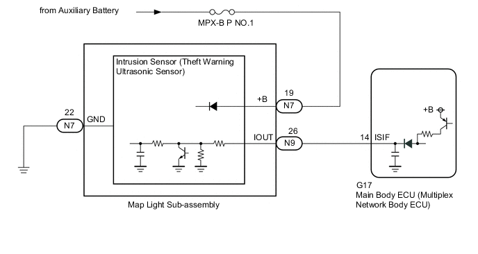
WIRING DIAGRAM
CAUTION / NOTICE / HINT
Note
-
Inspect the fuses for circuits related to this system before performing the following procedure.
-
If the main body ECU (multiplex network body ECU) is replaced, refer to the Service Bulletin.
PROCEDURE
-
READ VALUE USING GTS (Intrusion Sensor, Intrusion Sensor Sound Detect)
-
Connect the GTS to the DLC3.
-
Turn the power switch on (IG).
-
Turn the GTS on.
-
Enter the following menus: Body Electrical / Main Body / Data List.
-
Read the Data List according to the display on the GTS.
Tech Tips
When performing the above inspection, have the electrical key transmitter sub-assembly in the vehicle exterior detection area to perform certification (this prevents the alarm from sounding).
Note
Make sure that all windows are closed.
-
Make a metal-on-metal striking sound (such as by shaking keys) near the intrusion sensor (theft warning ultrasonic sensor) and check the Data List.
Body Electrical > Main Body > Data ListTester Display Measurement Item Range Normal Condition Diagnostic Note Intrusion Sensor Sound Detect Sound detection status of the intrusion sensor (theft warning ultrasonic sensor)*1*2 ON or OFF ON: Sound detected
OFF: Sound not detected
Only displays "ON" on the Data List once. When checking again, disconnect and reconnect the GTS.
Body Electrical > Main Body > Data ListTester Display Intrusion Sensor Sound Detect
-
*1: w/o Door Ajar Warning Buzzer Function
Note
*2: Perform the intrusion sensor (theft warning ultrasonic sensor) operation inspection with the GTS disconnected.
-
-
From inside the vehicle, put your hand in front of the intrusion sensor (theft warning ultrasonic sensor) and move it back and forth a distance of 0.3 m (0.984 ft.) and check the Data List.
Body Electrical > Main Body > Data ListTester Display Measurement Item Range Normal Condition Diagnostic Note Intrusion Sensor Status of the intrusion sensor (theft warning ultrasonic sensor) detection ON or OFF ON: Intrusion sensor (theft warning ultrasonic sensor) detected
OFF: Intrusion sensor (theft warning ultrasonic sensor) not detected
-
Body Electrical > Main Body > Data ListTester Display Intrusion Sensor OK The GTS display changes correctly in response to the detection condition of the intrusion sensor (theft warning ultrasonic sensor). Result Proceed to OK NG
OK 
PROCEED TO NEXT SUSPECTED AREA SHOWN IN PROBLEM SYMPTOMS TABLE Click here
NG 
-
-
CHECK WAVEFORM (INTRUSION SENSOR [THEFT WARNING ULTRASONIC SENSOR]) (IOUT)
-
Using an oscilloscope, check the waveform.
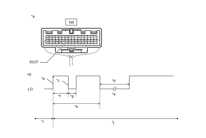
*a Component with harness connected
(Map Light Sub-assembly)
*b IOUT Initial Signal *c IOUT Initial Response *d Approximately 1.0 second *e Initial Diagnosis *f Approximately 1.0 to 1.6 seconds *g Approximately 0.05 seconds *h Approximately 5.5 seconds *i Disarmed State *j Arming Preparation State Measurement Condition Tester Connection Condition Tool Setting Specified Condition N9-26 (IOUT) - Body ground Theft deterrent system is set (system changes from disarmed state to arming preparation state) 2 V/DIV., 100 ms./DIV. The waveform displays properly (HI is 6.5 V or higher and LO is below 1 V). Tech Tips
-
If the intrusion sensor (theft warning ultrasonic sensor) is normal, an initial response is output in response to the HI input from the main body ECU (multiplex network body ECU).
-
If the waveform output remains LO, there may be a problem with the main body ECU (multiplex network body ECU), as there is no input from the main body ECU (multiplex network body ECU).
Result Proceed to OK NG -
NG
REPLACE MAIN BODY ECU (MULTIPLEX NETWORK BODY ECU) Click here
OK
-
-
CHECK HARNESS AND CONNECTOR (MAIN BODY ECU (MULTIPLEX NETWORK BODY ECU) - MAP LIGHT SUB-ASSEMBLY)
-
Disconnect the G17 main body ECU (multiplex network body ECU) connector.
-
Disconnect the N9 map light sub-assembly connector.
-
Measure the resistance according to the value(s) in the table below.
Standard Resistance Tester Connection Condition Specified Condition G17-14 (ISIF) - N9-26 (IOUT) Always Below 1 Ω G17-14 (ISIF) or N9-26 (IOUT) - Other terminals and body ground Always 10 kΩ or higher Result Proceed to OK NG
NG
REPAIR OR REPLACE HARNESS OR CONNECTOR
OK
-
-
INSPECT MAP LIGHT SUB-ASSEMBLY
-
Remove the map light sub-assembly.
-
Measure the resistance according to the value(s) in the table below.
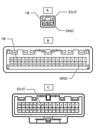
Standard Resistance Tester Connection Condition Specified Condition A-1(GND) - B-22(GND) Always Below 1 Ω A-2(IOUT) - C-26(IOUT) Always Below 1 Ω A-4(+B) - B-19(+B) Always Below 1 Ω Result Proceed to OK NG
OK
REPLACE INTRUSION SENSOR (THEFT WARNING ULTRASONIC SENSOR) Click here
NG
REPLACE MAP LIGHT SUB-ASSEMBLY Click here
-