POWER DOOR LOCK CONTROL SYSTEM TERMINALS OF ECU
-
CHECK INSTRUMENT PANEL JUNCTION BLOCK ASSEMBLY AND MAIN BODY ECU (MULTIPLEX NETWORK BODY ECU)
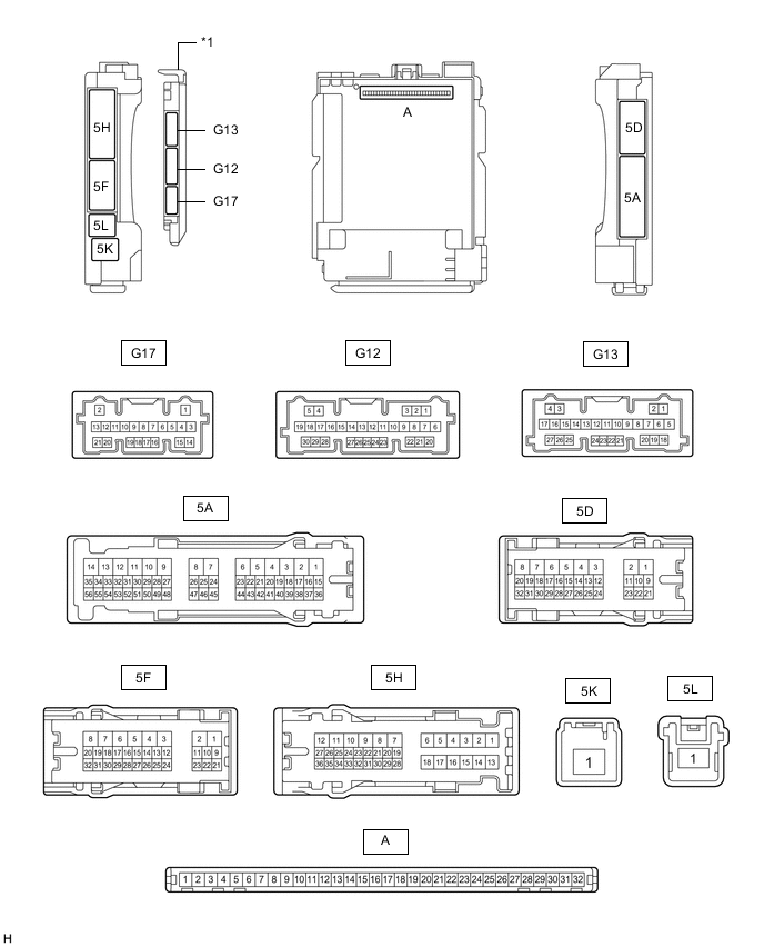
*1 Main Body ECU (Multiplex Network Body ECU) - -
-
*1: for LHD
-
*2: for RHD
-
Remove the main body ECU (multiplex network body ECU) from the instrument panel junction block assembly.
-
Reconnect the instrument panel junction block assembly connectors.
-
Measure the voltage and resistance according to the value(s) in the table below.
Tester Connection Wiring Color Input/Output Terminal Description Condition Specified Condition Related Data List Item A-11 (GND1) - Body ground - - Ground Always Below 1 Ω - A-30 (ACC) - Body ground - Input ACC power supply Power switch on (ACC) 11 to 14 V ACC SW Power switch off Below 1 V A-31 (BECU) - Body ground - Input Auxiliary battery power supply Power switch off 11 to 14 V - A-32 (IG) - Body ground - Input IG power supply Power switch on (IG) 11 to 14 V IG SW Power switch off Below 1 V -
Install the main body ECU (multiplex network body ECU) to the instrument panel junction block assembly.
-
Measure the voltage and check for pulses according to the value(s) in the table below.
Tester Connection Wiring Color Input/Output Terminal Description Condition Specified Condition Related Data List Item G12-1 (FLCY) - Body ground R - Body ground Input Front door courtesy light switch assembly LH input Front door LH open → closed Below 1 V → 4.7 to 5.3 V FL Door Courtesy SW G12-6 (FRCY) - Body ground SB - Body ground*1
R - Body ground*2
Input Front door courtesy light switch assembly RH input Front door RH open → closed Below 1 V → 4.7 to 5.3 V FR Door Courtesy SW 5H-26 (LCTY) - Body ground*1 G - Body ground Input Rear door courtesy light switch assembly LH input Rear door LH open → closed Below 1 V → 4.7 to 5.3 V RL Door Courtesy SW 5A-42 (LCTY) - Body ground*2 G - Body ground Input Rear door courtesy light switch assembly LH input Rear door LH open → closed Below 1 V → 4.7 to 5.3 V RL Door Courtesy SW 5D-19 (RCTY) - Body ground*1 R - Body ground Input Rear door courtesy light switch assembly RH input Rear door RH open → closed Below 1 V → 4.7 to 5.3 V RR Door Courtesy SW 5H-26 (RCTY) - Body ground*2 R - Body ground Input Rear door courtesy light switch assembly RH input Rear door RH open → closed Below 1 V → 4.7 to 5.3 V G17-18 (L2) - Body ground Y - Body ground Input Driver and front passenger door key-linked lock input Driver or front passenger door key cylinder turned to neutral position → on (lock) Pulse generation → Below 1 V Door Key SW-Lock G17-17 (UL3) - Body ground LG - Body ground Input Driver door key-linked unlock input Driver door key cylinder turned to neutral position → on (unlock) Pulse generation → Below 1 V D Door Key SW-UL 5A-2 (ACT+) - Body ground LA-G - Body ground Output Door lock motor lock drive output Door control switch or door key cylinder off → on (lock) Below 1 V → 11 to 14 V → Below 1 V - 5H-18 (ACT+) - Body ground LA-G - Body ground Output Door lock motor lock drive output Door control switch or door key cylinder off → on (lock) Below 1 V → 11 to 14 V → Below 1 V - 5H-6 (ACT+) - Body ground LA-G - Body ground Output Door lock motor lock drive output Door control switch or door key cylinder off → on (lock) Below 1 V → 11 to 14 V → Below 1 V - 5A-1 (ACT-) - Body ground LA-LG - Body ground Output Front passenger door lock motor unlock drive output Door control switch front passenger door key cylinder off → on (unlock) Below 1 V → 11 to 14 V → Below 1 V - 5H-7 (ACT-) - Body ground LA-LG - Body ground Output Front passenger door lock motor unlock drive output Door control switch front passenger door key cylinder off → on (unlock) Below 1 V → 11 to 14 V → Below 1 V - 5H-8 (ACTD) - Body ground LA-LG - Body ground*1
LA-R - Body ground*2
Output Driver door lock motor unlock drive output Door control switch or driver door key cylinder off → on (unlock) Below 1 V → 11 to 14 V → Below 1 V - 5D-14 (LSFR) - Body ground*1 GR - Body ground Input Front door RH unlock detection switch input Front door RH locked → unlocked Pulse generation → Below 1 V FR Door Lock Pos 5H-31 (LSFR) - Body ground*2 GR - Body ground Input Front door RH unlock detection switch input Front door RH locked → unlocked Pulse generation → Below 1 V FR Door Lock Pos 5H-31 (LSFL) - Body ground*1 P - Body ground Input Front door LH unlock detection switch input Front door LH locked → unlocked Pulse generation → Below 1 V FL Door Lock Pos 5A-15 (LSFL) - Body ground*2 B - Body ground Input Front door LH unlock detection switch input Front door LH locked → unlocked Pulse generation → Below 1 V FL Door Lock Pos G13-20 (LSWR) - Body ground B - Body ground Input Rear door RH unlock detection switch input Rear door RH locked → unlocked Pulse generation → Below 1 V RR-Door Lock Pos SW 5H-21 (LSWL) - Body ground*1 B - Body ground Input Rear door LH unlock detection switch input Rear door LH locked → unlocked Pulse generation → Below 1 V RL-Door Lock Pos SW 5D-12 (LSWL) - Body ground*2 SB - Body ground Input Rear door LH unlock detection switch input Rear door LH locked → unlocked Pulse generation → Below 1 V RL-Door Lock Pos SW 5D-13 (L1) - Body ground*1 P - Body ground Input Front passenger door control switch input Front passenger door control switch off → on (lock) Pulse generation → Below 1 V Door Lock Switch Status 5A-38 (L1) - Body ground*2 P - Body ground Input Front passenger door control switch input Front passenger door control switch off → on (lock) Pulse generation → Below 1 V Door Lock Switch Status 5D-12 (UL1) - Body ground*1 R - Body ground Input Front passenger door control switch input Front passenger door control switch off → on (unlock) Pulse generation → Below 1 V Door Unlock Switch Status 5A-39 (UL1) - Body ground*2 R - Body ground Input Front passenger door control switch input Front passenger door control switch off → on (unlock) Pulse generation → Below 1 V Door Unlock Switch Status 5A-46 (GSW) - Body ground B - Body ground Input Collision detection input Power switch on (IG) 2.9 to 4.2 V -
-
-
CHECK FRONT MULTIPLEX NETWORK DOOR ECU LH (w/ Double Locking System)

-
Disconnect the H31 front multiplex network door ECU LH connector.
-
Measure the voltage and resistance according to the value(s) in the table below.
Terminal No. (Symbols) Wiring Color Terminal Description Condition Specified Condition H31-1 (GND) - Body ground W-B - Body ground Ground Always Below 1 Ω H31-6 (BDR) - H31-1 (GND) R - W-B Battery power supply Power switch off 11 to 14 V H31-4 (CPUB) - H31-1 (GND) L - W-B Battery power supply Power switch off 11 to 14 V If the result is not as specified, there may be a malfunction on the wire harness side.
-
Reconnect the H31 front multiplex network door ECU LH connector.
-
Measure the voltage according to the value(s) in the table below.
Terminal No. (Symbols) Wiring Color Terminal Description Condition Specified Condition H29-5 (A1+) - H31-1 (GND) LA-R - W-B Double lock motor drive output Wireless or entry operation performed to set double lock 11 to 14 V Wireless or entry operation not performed Below 1 V H29-6 (A1-) - H31-1 (GND) LA-L - W-B Double lock motor drive output Wireless or entry operation performed to unset double lock 11 to 14 V Wireless or entry operation not performed Below 1 V H29-24 (DBLS) - H29-4 (DBE) V - BR Double lock position switch signal input Double lock UNSET Pulse generation Double lock SET Below 1 V
-
-
CHECK FRONT MULTIPLEX NETWORK DOOR ECU RH (w/ Double Locking System)

-
Disconnect the H12 front multiplex network door ECU RH connector.
-
Measure the voltage and resistance according to the value(s) in the table below.
Terminal No. (Symbols) Wiring Color Terminal Description Condition Specified Condition H12-1 (GND) - Body ground W-B - Body ground Ground Always Below 1 Ω H12-6 (BDR) - H12-1 (GND) R - W-B Battery power supply Power switch off 11 to 14 V H12-4 (CPUB) - H12-1 (GND) L - W-B Battery power supply Power switch off 11 to 14 V If the result is not as specified, there may be a malfunction on the wire harness side.
-
Reconnect the H12 front multiplex network door ECU LH connector.
-
Measure the voltage according to the value(s) in the table below.
Terminal No. (Symbols) Wiring Color Terminal Description Condition Specified Condition H10-5 (A1+) - H12-1 (GND) LA-R - W-B Double lock motor drive output Wireless or entry operation performed to set double lock 11 to 14 V Wireless or entry operation not performed Below 1 V H10-6 (A1-) - H12-1 (GND) LA-L - W-B Double lock motor drive output Wireless or entry operation performed to unset double lock 11 to 14 V Wireless or entry operation not performed Below 1 V H10-24 (DBLS) - H10-4 (DBE) V - BR Double lock position switch signal input Double lock UNSET Pulse generation Double lock SET Below 1 V
-
-
CHECK REAR MULTIPLEX NETWORK DOOR ECU LH (w/ Double Locking System)

-
Disconnect the K21 rear multiplex network door ECU LH connector.
-
Measure the voltage and resistance according to the value(s) in the table below.
Terminal No. (Symbols) Wiring Color Terminal Description Condition Specified Condition K21-1 (GND) - Body ground LA - Body ground Ground Always Below 1 Ω K21-4 (BDR) - K21-1 (GND) L - LA Battery power supply Power switch off 11 to 14 V K21-11 (CPUB) - K21-1 (GND) L - LA Battery power supply Power switch off 11 to 14 V If the result is not as specified, there may be a malfunction on the wire harness side.
-
Reconnect the K21 rear multiplex network door ECU LH connector.
-
Measure the voltage according to the value(s) in the table below.
Terminal No. (Symbols) Wiring Color Terminal Description Condition Specified Condition K20-5 (A1+) - K21-1 (GND) LA-GR - LA Double lock motor drive output Wireless or entry operation performed to set double lock 11 to 14 V Wireless or entry operation not performed Below 1 V K20-6 (A1-) - K21-1 (GND) LA-G - LA Double lock motor drive output Wireless or entry operation performed to unset double lock 11 to 14 V Wireless or entry operation not performed Below 1 V K20-24 (DBLS) - K20-4 (DLE1) GR - BE Double lock position switch signal input Double lock UNSET Pulse generation Double lock SET Below 1 V
-
-
CHECK REAR MULTIPLEX NETWORK DOOR ECU RH (w/ Double Locking System)

-
Disconnect the K7 rear multiplex network door ECU RH connector.
-
Measure the voltage and resistance according to the value(s) in the table below.
Terminal No. (Symbols) Wiring Color Terminal Description Condition Specified Condition K7-1 (GND) - Body ground LA - Body ground Ground Always Below 1 Ω K7-4 (BDR) - K7-1 (GND) B - LA Battery power supply Power switch off 11 to 14 V K7-11 (CPUB) - K7-1 (GND) L - LA Battery power supply Power switch off 11 to 14 V If the result is not as specified, there may be a malfunction on the wire harness side.
-
Reconnect the K7 rear multiplex network door ECU RH connector.
-
Measure the voltage according to the value(s) in the table below.
Terminal No. (Symbols) Wiring Color Terminal Description Condition Specified Condition K6-5 (A1+) - K7-1 (GND) LA-GR - LA Double lock motor drive output Wireless or entry operation performed to set double lock 11 to 14 V Wireless or entry operation not performed Below 1 V K6-6 (A1-) - K7-1 (GND) LA-G - LA Double lock motor drive output Wireless or entry operation performed to unset double lock 11 to 14 V Wireless or entry operation not performed Below 1 V K6-24 (DBLS) - K6-4 (DLE1) GR - BE Double lock position switch signal input Double lock UNSET Pulse generation Double lock SET Below 1 V
-
-
CHECK AIRBAG ECU ASSEMBLY