CAUTION / NOTICE / HINT
-
Use the same procedure for RHD and LHD vehicles.
-
The procedure listed below is for LHD vehicles.
PROCEDURE
- Click here
INSTALL NETWORK GATEWAY ECU
-
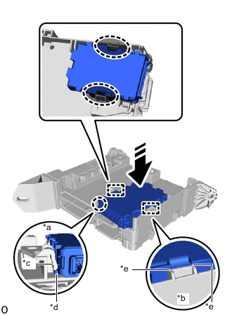
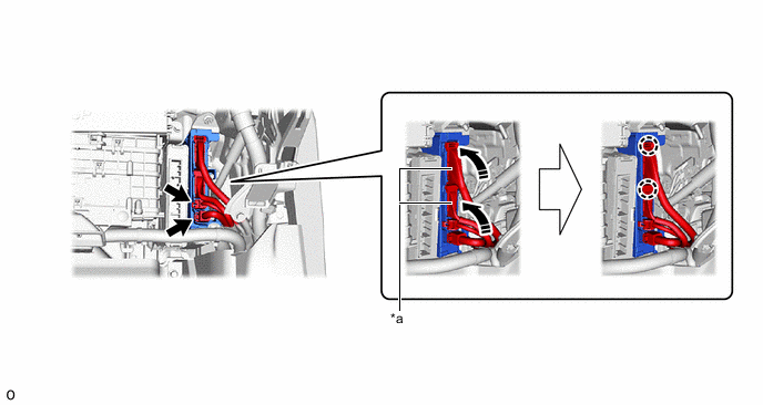
*a Lock Part *b Guide Part *c Passenger Side Junction Block Assembly Claw *d Protrusion of the Network Gateway ECU *e Check that it is securely installed 
Pressing Area 
Install in this Direction Align the guide and attach the claw to install the network gateway ECU.
Note:
-
For the lock, make sure that the claw of the passenger side junction block assembly goes over the protrusion of the network gateway ECU.
-
For the guide, make sure that the network gateway ECU is securely installed to the passenger side junction block assembly.
-
-
- Click here
INSTALL PASSENGER SIDE JUNCTION BLOCK ASSEMBLY WITH NETWORK GATEWAY ECU
-
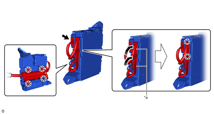
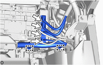
*a Lever Connector - - Rotate in this Direction - - Attach the claw to connect the 2 lever connectors.
Note:Be sure to connect the lever connector securely.
-
Connect the connector.
-
Attach the claw.
-
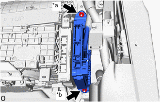
*a Nut (A) *b Nut (B) w/ VGRS:
-
Install the nut (A).
Note: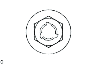
If the removed nut is the same shape as that shown in the illustration, replace it the supplied replacement part.
8.0 N*m 82 kgf*cm 71 in.*lbf
-
-
w/o VGRS:
-
Install the nut (A) and nut (B).
Note:
If the removed nut is the same shape as that shown in the illustration, replace it the supplied replacement part.
8.0 N*m 82 kgf*cm 71 in.*lbf
-
-
*a Lever Connector - - Rotate in this Direction - - Connect the 2 connectors.
-
Attach the claw to connect the 2 lever connectors.
Note:Be sure to connect the lever connector securely.
-
Connect the 4 connectors.
-
Attach the clamp.
-
- Click here
INSTALL GLOVE COMPARTMENT DOOR ASSEMBLY (w/o VGRS)
- Click here
INSTALL GLOVE COMPARTMENT DOOR PAD PLATE (w/o VGRS)
- Click here
INSTALL LOWER INSTRUMENT PANEL FINISH PANEL ASSEMBLY WITH AIR CONDITIONING CONTROL ASSEMBLY (w/o VGRS)
- Click here
INSTALL LOWER NO. 1 INSTRUMENT PANEL PAD SUB-ASSEMBLY (w/o VGRS)
- Click here
INSTALL INSTRUMENT SIDE PANEL LH (w/o VGRS)
- Click here
INSTALL LOWER NO. 2 INSTRUMENT PANEL AIRBAG ASSEMBLY (w/o VGRS)
- Click here
INSTALL FRONT STEERING CONTROL ECU (w/ VGRS)