POWER DOOR LOCK CONTROL SYSTEM Double Lock Function does not Operate Properly
DESCRIPTION
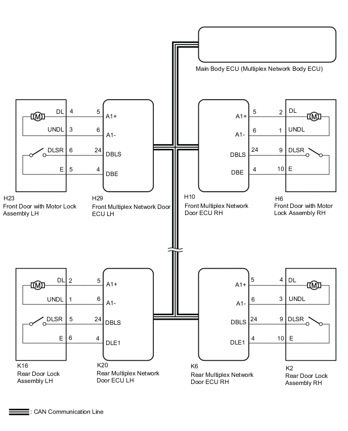
All the doors except the luggage compartment door have the double lock function. This system is set and unset by the main body ECU. When the main body ECU sends a request signal to each door ECU to set or unset the double lock function, the double lock motor built into each door lock operates.
WIRING DIAGRAM
CAUTION / NOTICE / HINT
Note
-
The power door lock control system uses the CAN communication system. Inspect the communication function by following How to Proceed with Troubleshooting. Troubleshoot the power door lock control system after confirming that the communication systems are functioning properly.
-
If the main body ECU (multiplex network body ECU) is replaced, refer to the Service Bulletin.
PROCEDURE
-
CHECK WIRELESS DOOR LOCK CONTROL SYSTEM
-
Check that the doors can be locked and unlocked normally using the wireless operation.
OK Doors can be locked and unlocked normally using wireless operation. Result Proceed to OK NG
NG 
GO TO WIRELESS DOOR LOCK CONTROL SYSTEM Click here
OK 
-
-
CHECK DOUBLE LOCK OPERATION
-
Check the double lock operation.
Result Result Proceed to All doors cannot be double-locked or double-unlocked. A Only front left door cannot be double-locked or double-unlocked. B Only front right door cannot be double-locked or double-unlocked. C Only rear left door cannot be double-locked or double-unlocked. D Only rear right door cannot be double-locked or double-unlocked. E
A
REPLACE MAIN BODY ECU (MULTIPLEX NETWORK BODY ECU) Click here
C 
INSPECT FRONT DOOR WITH MOTOR LOCK ASSEMBLY RH Click here
D
INSPECT REAR DOOR LOCK ASSEMBLY LH Click here
E
INSPECT REAR DOOR LOCK ASSEMBLY RH Click here
B
-
-
INSPECT FRONT DOOR WITH MOTOR LOCK ASSEMBLY LH
-
Remove the front door with motor lock assembly LH.
-
Inspect the front door with motor lock assembly LH.
Result Proceed to OK NG
NG
REPLACE FRONT DOOR WITH MOTOR LOCK ASSEMBLY LH Click here
OK
-
-
CHECK HARNESS AND CONNECTOR (FRONT DOOR WITH MOTOR LOCK ASSEMBLY LH - FRONT MULTIPLEX NETWORK DOOR ECU LH)
-
Disconnect the H23 front door with motor lock assembly LH connector.
-
Disconnect the H29 front multiplex network door ECU LH connector.
-
Measure the resistance according to the value(s) in the table below.
Standard Resistance Tester Connection Condition Specified Condition H23-4 (DL) - H29-5 (A1+) Always Below 1 Ω H23-3 (UNDL) - H29-6 (A1-) Always Below 1 Ω H23-6 (DLSR) - H29-24 (DBLS) Always Below 1 Ω H23-5 (E) - H29-4 (DBE) Always Below 1 Ω H23-4 (DL) or H29-5 (A1+) - Other terminals and body ground Always 10 kΩ or higher H23-3 (UNDL) or H29-6 (A1-) - Other terminals and body ground Always 10 kΩ or higher H23-6 (DLSR) or H29-24 (DBLS) - Other terminals and body ground Always 10 kΩ or higher H23-5 (E) or H29-4 (DBE) - Other terminals and body ground Always 10 kΩ or higher Result Proceed to OK NG
OK
REPLACE FRONT MULTIPLEX NETWORK DOOR ECU LH Click here
NG
REPAIR OR REPLACE HARNESS OR CONNECTOR
-
-
INSPECT FRONT DOOR WITH MOTOR LOCK ASSEMBLY RH
-
Remove the front door with motor lock assembly RH.
-
Inspect the front door with motor lock assembly RH.
Result Proceed to OK NG
NG
REPLACE FRONT DOOR WITH MOTOR LOCK ASSEMBLY RH Click here
OK
-
-
CHECK HARNESS AND CONNECTOR (FRONT DOOR WITH MOTOR LOCK ASSEMBLY RH - FRONT MULTIPLEX NETWORK DOOR ECU RH)
-
Disconnect the H6 front door with motor lock assembly RH connector.
-
Disconnect the H10 front multiplex network door ECU RH connector.
-
Measure the resistance according to the value(s) in the table below.
Standard Resistance Tester Connection Condition Specified Condition H6-2 (DL) - H10-5 (A1+) Always Below 1 Ω H6-1 (UNDL) - H10-6 (A1-) Always Below 1 Ω H6-9 (DLSR) - H10-24 (DBLS) Always Below 1 Ω H6-10 (E) - H10-4 (DBE) Always Below 1 Ω H6-2 (DL) or H10-5 (A1+) - Other terminals and body ground Always 10 kΩ or higher H6-1 (UNDL) or H10-6 (A1-) - Other terminals and body ground Always 10 kΩ or higher H6-9 (DLSR) or H10-24 (DBLS) - Other terminals and body ground Always 10 kΩ or higher H6-10 (E) or H10-4 (DBE) - Other terminals and body ground Always 10 kΩ or higher Result Proceed to OK NG
OK
REPLACE FRONT MULTIPLEX NETWORK DOOR ECU RH Click here
NG
REPAIR OR REPLACE HARNESS OR CONNECTOR
-
-
INSPECT REAR DOOR LOCK ASSEMBLY LH
-
Remove the rear door lock assembly LH.
-
Inspect the rear door lock assembly LH.
Result Proceed to OK NG
NG
REPLACE REAR DOOR LOCK ASSEMBLY LH Click here
OK
-
-
CHECK HARNESS AND CONNECTOR (REAR DOOR LOCK ASSEMBLY LH - REAR MULTIPLEX NETWORK DOOR ECU LH)
-
Disconnect the K16 rear door lock assembly LH connector.
-
Disconnect the K20 rear multiplex network door ECU LH connector.
-
Measure the resistance according to the value(s) in the table below.
Standard Resistance Tester Connection Condition Specified Condition K16-2 (DL) - K20-5 (A1+) Always Below 1 Ω K16-1 (UNDL) - K20-6 (A1-) Always Below 1 Ω K16-5 (DLSR) - K20-24 (DBLS) Always Below 1 Ω K16-6 (E) - K20-4 (DLE1) Always Below 1 Ω K16-2 (DL) or K20-5 (A1+) - Other terminals and body ground Always 10 kΩ or higher K16-1 (UNDL) or K20-6 (A1-) - Other terminals and body ground Always 10 kΩ or higher K16-5 (DLSR) or K20-24 (DBLS) - Other terminals and body ground Always 10 kΩ or higher K16-6 (E) or K20-4 (DLE1) - Other terminals and body ground Always 10 kΩ or higher Result Proceed to OK NG
OK
REPLACE REAR MULTIPLEX NETWORK DOOR ECU LH Click here
NG
REPAIR OR REPLACE HARNESS OR CONNECTOR
-
-
INSPECT REAR DOOR LOCK ASSEMBLY RH
-
Remove the rear door lock assembly RH.
-
Inspect the rear door lock assembly RH.
Result Proceed to OK NG
NG
REPLACE REAR DOOR LOCK ASSEMBLY RH Click here
OK
-
-
CHECK HARNESS AND CONNECTOR (REAR DOOR LOCK ASSEMBLY RH - REAR MULTIPLEX NETWORK DOOR ECU RH)
-
Disconnect the K2 rear door lock assembly RH connector.
-
Disconnect the K6 rear multiplex network door ECU RH connector.
-
Measure the resistance according to the value(s) in the table below.
Standard Resistance Tester Connection Condition Specified Condition K2-4 (DL) - K6-5 (A1+) Always Below 1 Ω K2-3 (UNDL) - K6-6 (A1-) Always Below 1 Ω K2-9 (DLSR) - K6-24 (DBLS) Always Below 1 Ω K2-10 (E) - K6-4 (DLE1) Always Below 1 Ω K2-4 (DL) or K6-5 (A1+) - Other terminals and body ground Always 10 kΩ or higher K2-3 (UNDL) or K6-6 (A1-) - Other terminals and body ground Always 10 kΩ or higher K2-9 (DLSR) or K6-24 (DBLS) - Other terminals and body ground Always 10 kΩ or higher K2-10 (E) or K6-4 (DLE1) - Other terminals and body ground Always 10 kΩ or higher Result Proceed to OK NG
OK
REPLACE REAR MULTIPLEX NETWORK DOOR ECU RH Click here
NG
REPAIR OR REPLACE HARNESS OR CONNECTOR
-