CAN COMMUNICATION SYSTEM DIAGNOSIS SYSTEM
-
CHECK FOR INSTALLED SYSTEMS (ECUS AND SENSORS) THAT USE CAN COMMUNICATION
-
The systems (ECUs and sensors) that use CAN communication vary depending on the vehicle and optional equipment. Check which systems (ECUs and sensors) are installed to the vehicle.
-
GTS display and installed systems
Tech Tips
The names of ECUs and sensors shown on the GTS display may differ from those shown in DTC Table by ECU.
Connected to Code ECU/Sensor Name GTS Display Applicability - CGW Central gateway ECU (network gateway ECU) - Installed on all vehicles V Bus DLC3 DLC3 - Installed on all vehicles Bus 1 GRS Swing grille actuator assembly Grill Shutter w/ Grille Shutter System F-CAM Forward recognition camera Front Camera Module w/ Pre-collision System (for Mono Camera Type) Object recognition camera Front Camera Module w/ Pre-collision System (for Stereo Camera Type) S-MR Front side radar sensor RH Front Side Radar Master w/ Pre-collision System (for Stereo Camera Type) F-MR Millimeter wave radar sensor assembly Front Radar w/ Pre-collision System DS Driving support ECU assembly Driving Support (Cruise Control-ACC) w/ Pre-collision System PAC Parking assist ECU Panoramic View Monitor / Circumference Monitoring Camera Control Module w/ Panoramic View Monitor System BSM Blind spot monitor sensor RH Blind Spot Monitor Master w/ Blind Spot Monitor System CS Clearance warning ECU assembly Clearance Warning (Clearance Sonar) Installed on all vehicles R-CA Rear television camera assembly Parking Assist Monitor System / Rear Camera Installed on all vehicles PSB Seat belt control ECU Seat Belt Control (Pre-Collision) w/ Pre-collision System (for Stereo Camera Type) Bus 2 SBW Shift control ECU Transmission Control Installed on all vehicles BRK Skid control ECU assembly Skid Control (ABS/VSC/TRC) Installed on all vehicles SBM Sub-battery with control assembly Sub Battery Module Installed on all vehicles F-MGC Inverter with converter assembly Motor Generator Installed on all vehicles HVB Battery ECU assembly HV Battery Installed on all vehicles ENG ECM ECM (Engine) Installed on all vehicles HV Hybrid vehicle control ECU assembly Hybrid Vehicle Control Installed on all vehicles Bus 3 AV Radio receiver assembly Display and Navigation (AVN) Installed on all vehicles YGW Bus buffer ECU Accessory Gateway w/ Bus Buffer ECU DCM Telematics transceiver DCM w/ Telematics Transceiver ANC Stereo component equalizer assembly Active Noise Control Installed on all vehicles R-DRR Rear multiplex network door ECU RH Rear Door RH (RR-Door) Installed on all vehicles R-DRL Rear multiplex network door ECU LH Rear Door LH (RL-Door) Installed on all vehicles BKD Luggage closer motor assembly Back Door Installed on all vehicles Bus 4 EPS Rack and pinion power steering gear assembly Power Steering (EPS) Installed on all vehicles BRK Skid control ECU assembly Skid Control (ABS/VSC/TRC) Installed on all vehicles ENG ECM ECM (Engine) Installed on all vehicles SRS Airbag ECU assembly Airbag Installed on all vehicles PUP Pedestrian detection ECU assembly Pedestrian Protection Installed on all vehicles STR Steering sensor Spiral cable (Steering Angle Sensor) Installed on all vehicles YGS Yaw rate sensor Yaw Rate Sensor Installed on all vehicles VGRS Front steering control ECU Steering Control (VGRS) w/ Variable Gear Ratio Steering System TPMS Tire pressure warning ECU and receiver Tire Pressure Installed on all vehicles SUS Suspension control ECU Suspension Control (Air Suspension) w/ Air Suspension System SUS1 Absorber control ECU Suspension Control (Air Suspension1) Installed on all vehicles PKB Parking brake ECU assembly Electric Parking Brake Installed on all vehicles DRS Rear steering control ECU DRS w/ Dynamic Rear Steering System OCS Occupant detection ECU Occupant Detection w/ Occupant Classification System HV Hybrid vehicle control ECU assembly Hybrid Vehicle Control Installed on all vehicles Bus 5 MB Main body ECU (multiplex network body ECU) Main Body Installed on all vehicles LITM Headlight ECU sub-assembly LH HL AutoLeveling/AFS/AHS Installed on all vehicles T&T Multiplex tilt and telescopic ECU Multiplex Tilt and Telescopic Installed on all vehicles SMT Certification ECU (smart key ECU assembly) Certification (Smart) Installed on all vehicles HUD Meter mirror sub-assembly Head Up Display w/ Headup Display System A/C Air conditioning amplifier assembly Air Conditioning Amplifier Installed on all vehicles R-CP Rear power seat switch (rear multi operation panel) Rear Console Switch w/ Rear Multi Operation Panel System LITS Headlight ECU sub-assembly RH HL AutoLeveling/AFS/AHS (Sub) Installed on all vehicles PST No. 2 position control ECU assembly P-Seat Installed on all vehicles F-DRL Front multiplex network door ECU LH Front Door LH/L-Mirror (FL-Door/L-Mirror) Installed on all vehicles DST Position control ECU assembly D-Seat Installed on all vehicles F-DRR Front multiplex network door ECU RH Front Door RH/R-Mirror (FR-Door/R-Mirror) Installed on all vehicles MET Combination meter assembly Combination Meter Installed on all vehicles
-
-
-
Description of "Communication Bus Check" Screen
Note
The following communication bus check screen is provided only as an example. This screen differs from the actual screen for this vehicle.
Tech Tips
The ECUs and sensors that are normally connected to the CAN communication system are displayed on the GTS.
-
Select "Communication Bus Check" on the menu screen of the GTS.
CAN Bus CheckTech Tips
If items are not selected correctly in the vehicle specification pop up screen, the name of the CAN junction connector to which the ECUs or sensors are connected may not be displayed on the "Communication Bus Check" screen.
-
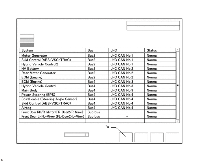
Confirm that the "Communication Bus Check" screen is displayed and the ECUs and sensors that are normally connected to the CAN communication system are displayed.
Tech Tips
-
Even if an ECU or sensor that is connected to a bus that is monitored by a bus monitoring ECU (gateway function equipped ECU) is not communicating, it will remain displayed on the "Communication Bus Check" screen.
-
When an ECU or sensor that is connected to a bus that is not monitored by a bus monitoring ECU (gateway function equipped ECU) is not displayed on the "Communication Bus Check" screen, it means that it is not communicating.
-
-
The default display setting selected on the combo box is ALL. When checking for ECUs or sensors for a specific bus, choose the bus from the drop down list. ALL, each bus, each sub bus and Central Gateway are listed in the drop down list.
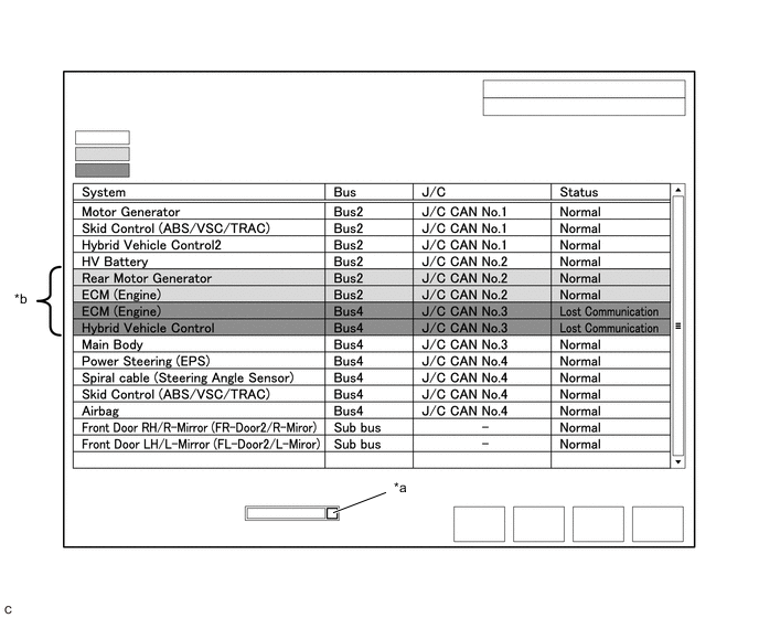
*a Combo box *b Background color is red or yellow Item Detail Combo box: ALL Displays all ECUs and sensors connected to the central bus and sub buses. Combo box: Bus Displays ECUs and sensors connected to the selected bus. Combo box: Sub bus Displays ECUs and sensors connected to the selected sub bus. Combo box: Central Gateway Displays all ECUs and sensors connected to the central bus. Note
-
When using the combo box, it may be possible to select a sub bus from the drop down list that does not have any connected ECUs or sensors. This is not a malfunction and occurs when there is no optional device connected to a sub bus which is monitored by a sub bus monitoring ECU (gateway function equipped ECU).
-
In the drop down list, all sub buses applicable to the model are displayed (e.g. LIN communication sub buses are also displayed). For information on sub buses necessary to diagnose the CAN communication system, refer to System Diagram.
Tech Tips
The background color of an ECU or sensor changes according to its connection status as indicated in the following table.
Description of "Communication Bus Check" Screen Bus Type Background Color Connection Status Bus White Communication has been normal. Yellow Communication stop occurred at least once since the start of the CAN bus check, but communication is currently occurring (unstable communication). Red Currently not communicating (either of the following):
-
Not communicating since the start of the CAN bus check
-
Communication occurred at least once since the start of the CAN bus check, but is currently not occurring.
Not displayed Either of the following:
-
The central gateway ECU (network gateway ECU) has an internal malfunction or cannot communicate with the GTS.*4
-
No ECUs or sensors are connected to the bus.*5
Sub bus with a gateway function equipped ECU that does not memorize connected ECUs or sensors*2 White Communication has been normal since the start of the CAN bus check. Yellow Communication stop occurred at least once since the start of the CAN bus check, but communication is currently occurring (unstable communication). Red Communication occurred at least once since the start of the CAN bus check, but is currently not occurring. Not displayed Communication stop has continued since the start of the CAN bus check.*1 Sub bus with a gateway function equipped ECU that memorizes connected ECUs and sensors*3 White Communication has been normal. Yellow Communication stop occurred at least once since the start of the CAN bus check, but communication is currently occurring (unstable communication). Red Currently not communicating (either of the following):
-
Not communicating since the start of the CAN bus check
-
Communication occurred at least once since the start of the CAN bus check, but is currently not occurring.
Not displayed Either of the following:
-
The gateway function equipped ECU cannot communicate with the central gateway ECU.*6
-
No ECUs or sensors are connected to the sub bus.*7
-
Gateway function equipped ECUs relay signals between ECUs and sensors connected to different buses.
-
*1: An ECU or sensor is installed to the vehicle but is not displayed on the "Communication Bus Check" screen.
-
*2: the gateway function equipped ECU does not memorize ECUs and sensors connected to its respective sub bus.
-
*3: the gateway function equipped ECU memorizes ECUs and sensors connected to its respective sub bus.
-
*4: When the central gateway ECU (network gateway ECU) has an internal malfunction or cannot communicate with the GTS, the name of buses, sub buses, ECUs and sensors will not be displayed.
-
*5: When no ECUs or sensors are connected to a bus, the message "There is no system found on the communication Bus." will be displayed.
-
*6: When a gateway function equipped ECU cannot communicate with the central gateway ECU (network gateway ECU), the name of sub buses and ECUs or sensors connected to the sub bus will not be displayed.
-
*7: When no ECUs or sensors are connected to the sub bus, the message "There is no system found on the communication Bus." will be displayed.
-
If there is no communication between the GTS and the vehicle, or no ECUs or sensors are displayed as connected, check the central gateway ECU (network gateway ECU) and diagnosis bus (The bus that connects the DLC3 to the central gateway ECU (network gateway ECU)) for malfunctions.
-
-
Monitor the screen for any ECU or sensor connection status changes for a period of 2 minutes.
Tech Tips
-
If an open occurs in one of the wires of a CAN branch line, it may interfere with the communication of other ECUs or sensors resulting in an incorrect state being displayed.
-
If the connection status changes intermittently during the inspection, repair the open in the branch line of the ECU or sensor that is not communicating, and then perform Communication Bus Check again.
-
-
-
Description of "Communication Bus Check (Detail)" Screen
Note
The following communication bus check screen is provided only as an example. This screen differs from the actual screen for this vehicle.
Tech Tips
The communication error history of ECUs or sensors which have communication error history can be displayed on the "Communication Bus Check (Detail)" screen.
-
Select "Communication Bus Check" on the menu screen of the GTS.
CAN Bus CheckTech Tips
If items are not selected correctly in the vehicle specification pop up screen, the name of the CAN junction connector to which the ECUs or sensors are connected may not be displayed on the "Communication Bus Check" screen.
-
Select "Detail" on the "Communication Bus Check" screen.
*a Communication Bus Check (Detail) - - -
Confirm that the "Communication Bus Check (Detail)" screen is displayed and the communication error history of the ECUs or sensors up to present is displayed.
Tech Tips
-
Lost Communication Time and Lost Communication Trip are only displayed for the central bus.
-
Lost Communication Time and Lost Communication Trip are not displayed for sub buses.
-
-
The default display setting selected on the combo box is ALL. When checking for ECUs or sensors for a specific bus, choose the bus from the drop down list. ALL, each bus, each sub bus and Central Gateway are listed in the drop down list.
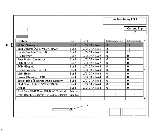
*a Combo box *b Background color is red Item Detail Combo box: ALL Displays all ECUs and sensors connected to the central bus and sub buses. Combo box: Bus Displays ECUs and sensors connected to the selected bus. Combo box: Sub bus Displays ECUs and sensors connected to the selected sub bus. Combo box: Central Gateway Displays all ECUs and sensors connected to the central bus. Bus Monitoring ECU Displays the gateway function equipped ECU which monitors the selected bus or sub bus. Current Trip Displays the total number of trips up to now* Lost Communication Time(s) Displays the longest period of time in seconds that the ECU or sensor connected to the central bus was not communicating. Lost Communication Trip Displays the trip in which the longest period of time that the ECU or sensor connected to the central bus was not communicating occurred.
-
*: If the component has been replaced with a new one, the total number of trips after the replacement is displayed.
Note
-
The Lost Communication Time column displays the longest period of time in seconds that the central gateway ECU (network gateway ECU) detected a communication stop in the respective ECU or sensor.
-
The Lost Communication Trip column displays the trip in which the central gateway ECU (network gateway ECU) detected the longest communication stop in the respective ECU or sensor.
-
When using the combo box, it may be possible to select a sub bus from the drop down list that does not have any connected ECUs or sensors. This is not a malfunction and occurs when there is no optional device connected to a sub bus which is monitored by a sub bus monitoring ECU (gateway function equipped ECU).
-
In the drop down list, all sub buses applicable to the model are displayed (e.g. LIN communication sub buses are also displayed). For information on sub buses necessary to diagnose CAN communication system, refer to the System Diagram.
Tech Tips
The background color of an ECU or sensor changes according to its connection status as indicated in the following table.
Description of "Communication Bus Check (Detail)" Screen Bus Type Background Color Connection Status Bus White Either of the following:
-
Communication has been normal.
-
Lost Communication Time is below 6 seconds.
Red Lost Communication Time is 6 seconds or more. Not displayed Either of the following:
-
The central gateway ECU (network gateway ECU) has an internal malfunction or cannot communicate with the GTS.*1
-
No ECUs or sensors are connected to the bus.*2
Sub bus White Lost Communication Time is displayed as "-". Not displayed Either of the following:
-
The gateway function equipped ECU cannot communicate with the central gateway ECU.*3
-
No ECUs or sensors are connected to the sub bus.*4
-
If there is no communication between the GTS and the vehicle, or no ECUs or sensors are displayed as connected, check the central gateway ECU (network gateway ECU) and diagnosis bus (The bus that connects the DLC3 to the central gateway ECU (network gateway ECU)) for malfunctions.
-
Lost Communication Time and Lost Communication Trip are not displayed for sub buses.
-
*1: When the central gateway ECU (network gateway ECU) has an internal malfunction or cannot communicate with the GTS, the name of buses, sub buses, ECUs and sensors will not be displayed.
-
*2: When no ECUs or sensors are connected to a bus, the message "There is no system found on the communication Bus." will be displayed.
-
*3: When a gateway function equipped ECU cannot communicate with the central gateway ECU (network gateway ECU), the name of sub buses and ECUs or sensors connected to the sub bus will not be displayed.
-
*4: When no ECUs or sensors are connected to the sub bus, the message "There is no system found on the communication Bus." will be displayed.
-
-
-
Communication Bus Check (Communication Malfunction Check)
Tech Tips
DTCs related to CAN communication are displayed for each ECU on the GTS.
-
Select "Communication Bus Check" on the menu screen of the GTS.
CAN Bus Check -
Select "Communication Malfunction Check" on the "Communication Bus Check" screen.

*a Communication Malfunction Check - - -
Confirm that the "Communication Malfunction Check" screen is displayed and CAN communication DTCs for each ECU are displayed.
Tech Tips
When there are no CAN communication DTCs stored, no DTCs will be displayed.
-
-
How to Use "Communication Bus Check" Screen in Inspection
Note
The following CAN bus wiring diagram or communication bus check screen is provided only as an example. This wiring diagram or screen differs from the actual one for this vehicle.
Tech Tips
-
If the CAN communication system is currently malfunctioning, it is recommended to use Communication Bus Check rather than Communication DTCs for determining the suspected area.
-
Turn the power switch on (IG), or perform the necessary operations to reproduce the problem symptom, select "Communication Bus Check" and wait approximately 2 minutes. Check the communication status of each ECU or sensor on the screen while performing this operation.
-
If the CAN communication system is currently malfunctioning, determine the suspected area through Communication Bus Check as follows:
Problem Symptoms Table Problem Symptom Pattern Display on Communication Bus Check Screen Suspected Area A Almost all of the ECUs and sensors connected to the malfunctioning CAN bus are displayed as not communicating on the "Communication Bus Check" screen.
-
Short between CAN bus lines (CANH and CANL)
-
Short to +B in a CAN bus line (CANH or CANL)
-
Short to ground in a CAN bus line (CANH or CANL)
B ECUs or sensors farther from the central gateway ECU (network gateway ECU) than the open in the wires are displayed as not communicating on the "Communication Bus Check" screen. Open in both wires of a main bus line in the central bus C One ECU or sensor is displayed as not communicating on the "Communication Bus Check" screen.
-
Open in both wires of a branch line connected to an ECU or sensor in the central bus
-
Internal malfunction of an ECU or sensor in the central bus
-
Malfunction in the power supplied to an ECU or sensor in the central bus
D No ECUs or sensors are displayed on the "Communication Bus Check" screen.
-
Internal malfunction of the central gateway ECU (network gateway ECU)
-
Malfunction in the power supplied to the central gateway ECU (network gateway ECU)
-
Open in both wires of the branch line in the diagnosis bus (DLC3 - Central gateway ECU (network gateway ECU))
-
Short between CAN bus lines (CANH and CANL) in the diagnosis bus (DLC3 - Central gateway ECU (network gateway ECU))
-
Short to +B in a CAN bus line (CANH or CANL) in the diagnosis bus (DLC3 - Central gateway ECU (network gateway ECU))
-
Short to ground in a CAN bus line (CANH or CANL) in the diagnosis bus (DLC3 - Central gateway ECU (network gateway ECU))
E One ECU or sensor is displayed as not communicating in multiple buses on the "Communication Bus Check" screen.
-
Internal malfunction of an ECU or sensor connected to multiple buses
-
Malfunction in the power supplied to an ECU or sensor connected to multiple buses
F Some ECUs or sensors are displayed as not communicating in the central bus and other ECUs or sensors are displayed as not communicating in a sub bus.
-
Open in a wire of a branch line connected to an ECU or sensor in the central bus
-
Internal malfunction of an ECU or sensor in the central bus
G A gateway function equipped ECU is displayed as not communicating in the central bus and ECUs and sensors connected to its respective sub bus are not displayed.
-
Open in both wires of a branch line connected to a gateway function equipped ECU
-
Internal malfunction of a gateway function equipped ECU
-
Malfunction in the power supplied to a gateway function equipped ECU
H One ECU or sensor is displayed as not communicating in a sub bus on the "Communication Bus Check" screen.
-
Open in both wires of a branch line connected to an ECU or sensor in a sub bus
-
Internal malfunction of an ECU or sensor in a sub bus
-
Malfunction in the power supplied to an ECU or sensor in a sub bus
I ECUs or sensors farther from the sub bus monitoring ECU (gateway function equipped ECU) than the open in the wires are displayed as not communicating on the "Communication Bus Check" screen. Open in both wires of a main bus line in a sub bus -
-
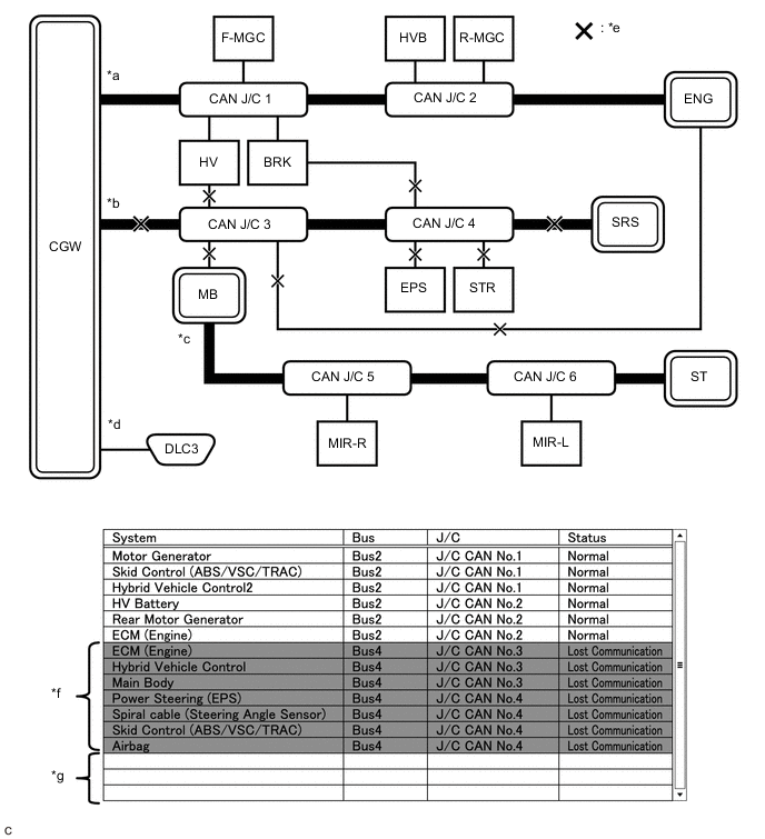
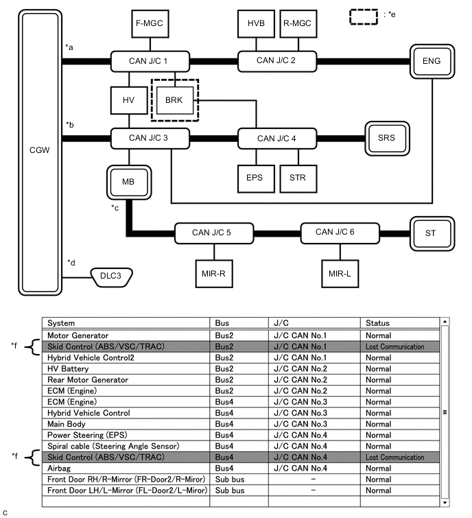
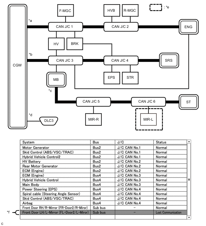
Problem Symptom Pattern A
Details of Malfunction
-
Short between CAN bus lines (CANH and CANL) in Bus 2
-
Short to +B in a CAN bus line (CANH or CANL) in Bus 2
-
Short to ground in a CAN bus line (CANH or CANL) in Bus 2
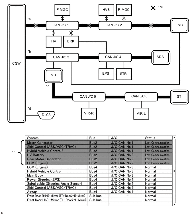
*a Bus 2 *b Bus 4 *c Sub bus *d Diagnosis bus *e Location of malfunction *f Background color is red Tech Tips
-
Due to the malfunction, almost all of the ECUs and sensors connected to Bus 2 will be displayed as not communicating and their background color will be red.
-
The malfunction in Bus 2 will not affect the other buses.
-
The malfunctioning part can be determined by inspecting for an open in the main bus line, a short between bus lines or a short to +B or ground.
-
Make sure to perform the inspection to measure resistances of buses to determine the cause of the malfunction.
Details of Malfunction
-
Short between CAN bus lines (CANH and CANL) in Bus 4
-
Short to +B in a CAN bus line (CANH or CANL) in Bus 4
-
Short to ground in a CAN bus line (CANH or CANL) in Bus 4
*a Bus 2 *b Bus 4 *c Sub bus *d Diagnosis bus *e Location of malfunction *f Background color is red *g Not displayed - - Tech Tips
-
Due to the malfunction, almost all of the ECUs and sensors connected to Bus 4 will be displayed as not communicating and their background color will be red.
-
The malfunction will not affect the other buses of the central bus. However, the sub bus connected to Bus 4 is likely to be affected. the gateway function equipped ECU connected to Bus 4 will not communicate and consequently the sub bus and its respective ECUs or sensors monitored by the gateway function equipped ECU (sub bus monitoring ECU) will not be displayed, indicating that the gateway function equipped ECU is not communicating with the central gateway ECU (network gateway ECU).
-
The malfunctioning part can be determined by inspecting for an open in the main bus line, a short between bus lines or a short to +B or ground.
-
Make sure to perform the inspection to measure resistances of buses to determine the cause of the malfunction.
-
-
Problem Symptom Pattern B
Details of Malfunction Open in both wires of the main bus line between the CGW and No. 1 CAN junction connector in Bus 2 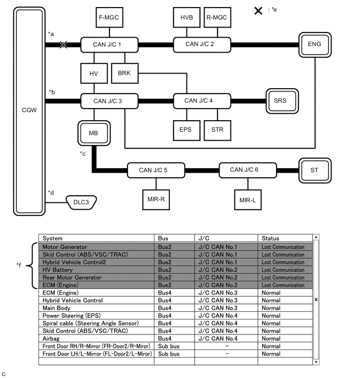
*a Bus 2 *b Bus 4 *c Sub bus *d Diagnosis bus *e Location of malfunction *f Background color is red Tech Tips
-
Due to the malfunction, almost all of the ECUs and sensors connected to Bus 2 will be displayed as not communicating and their background color will be red.
-
The malfunction in Bus 2 will not affect the other buses.
-
The malfunctioning part can be determined by inspecting for an open in the main bus line.
-
Make sure to perform the inspection to measure resistances of buses to determine the cause of the malfunction.
Details of Malfunction Open in both wires of the main bus line between the No. 1 CAN junction connector and No. 2 CAN junction connector in Bus 2 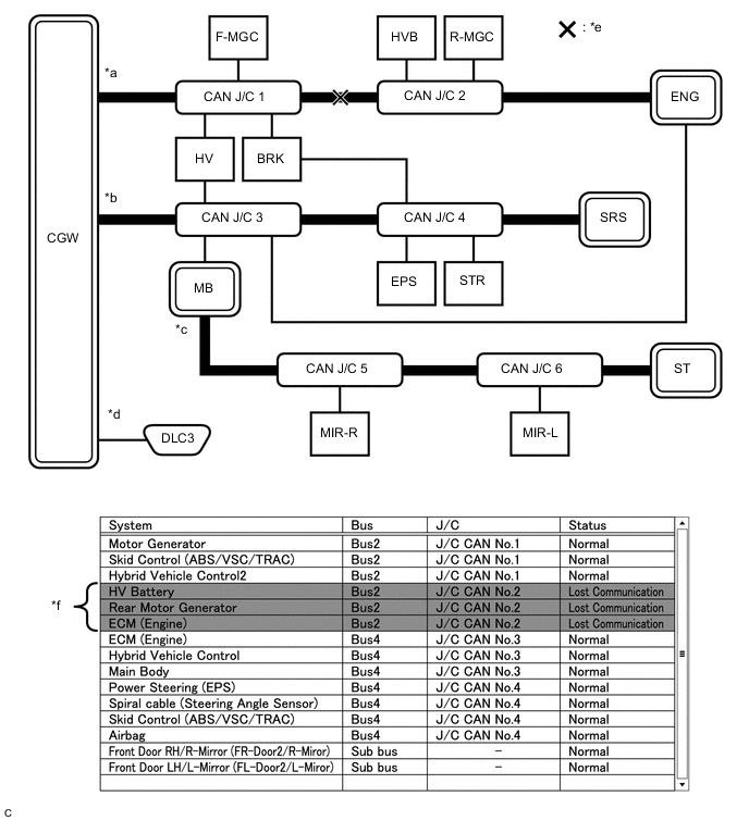
*a Bus 2 *b Bus 4 *c Sub bus *d Diagnosis bus *e Location of malfunction *f Background color is red Tech Tips
-
Due to the malfunction, ECUs or sensors farther from the CGW than the open in the wires will be displayed as not communicating and their background color will be red.
-
The malfunction in Bus 2 will not affect the other buses.
-
The malfunctioning part can be determined by inspecting for an open in the main bus line.
-
Make sure to perform the inspection to measure resistances of buses to determine the cause of the malfunction.
Details of Malfunction Open in both wires of the main bus line between the No. 2 CAN junction connector and ENG in Bus 2 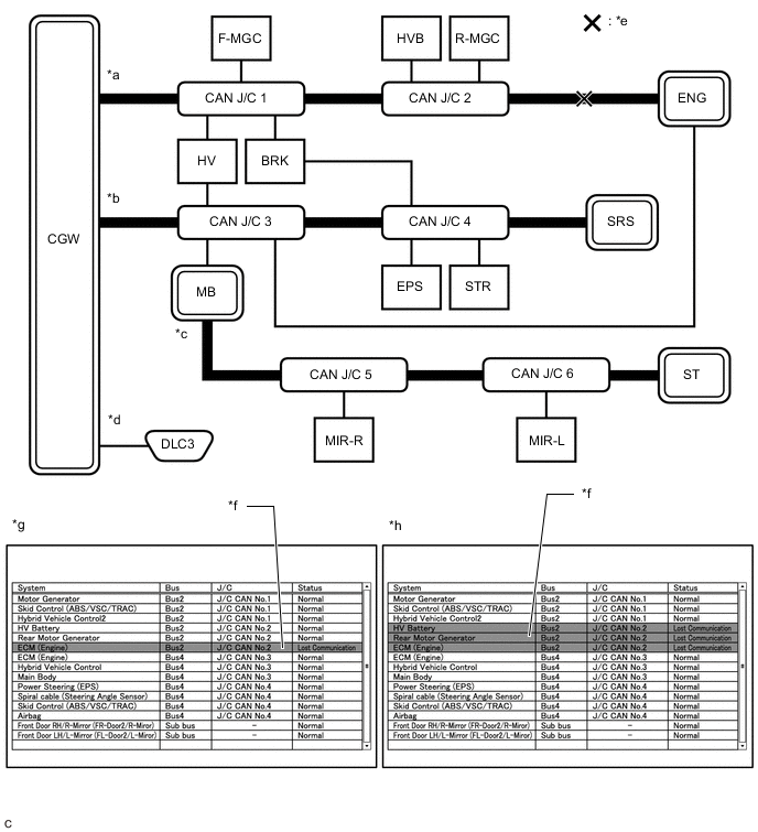
*a Bus 2 *b Bus 4 *c Sub bus *d Diagnosis bus *e Location of malfunction *f Background color is red *g Pattern 1 *h Pattern 2 Tech Tips
-
Even when the same part of the main bus line is open, depending on internal electrical noise which changes according to the position of the open in the line, the information displayed on the "Communication Bus Check" screen may differ.
-
In pattern 2, the information displayed may be the same as when there is an open in both wires in the main bus line between the No. 1 CAN junction connector and No. 2 CAN junction connector, which may make it difficult to determine the malfunctioning part.
-
The malfunction in Bus 2 will not affect the other buses.
-
Make sure to perform the inspection to measure resistances of buses to determine the cause of the malfunction.
-
-
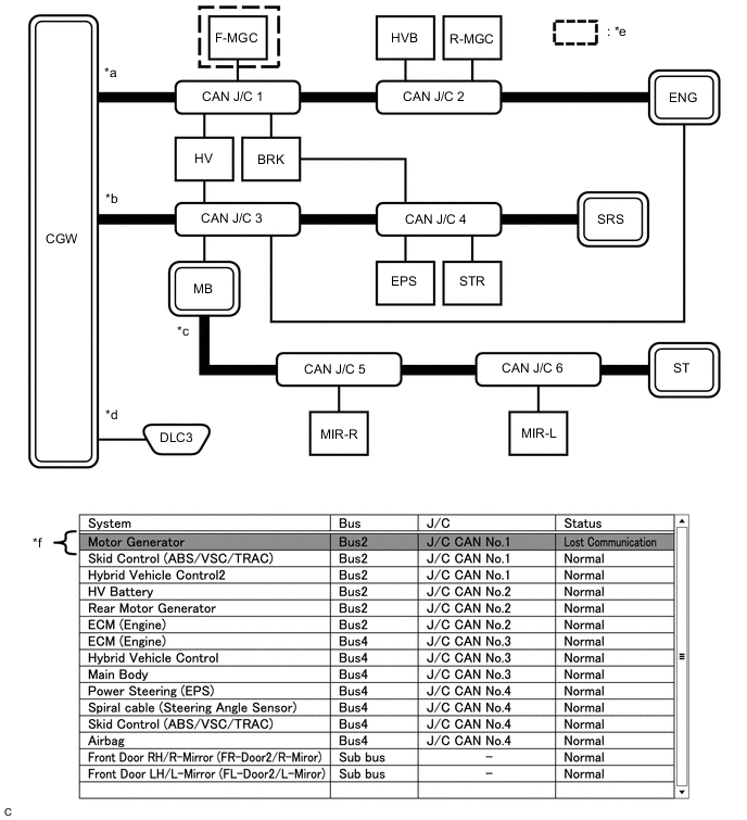
Problem Symptom Pattern C
Details of Malfunction Open in both wires of the branch line connected to F-MGC in Bus 2 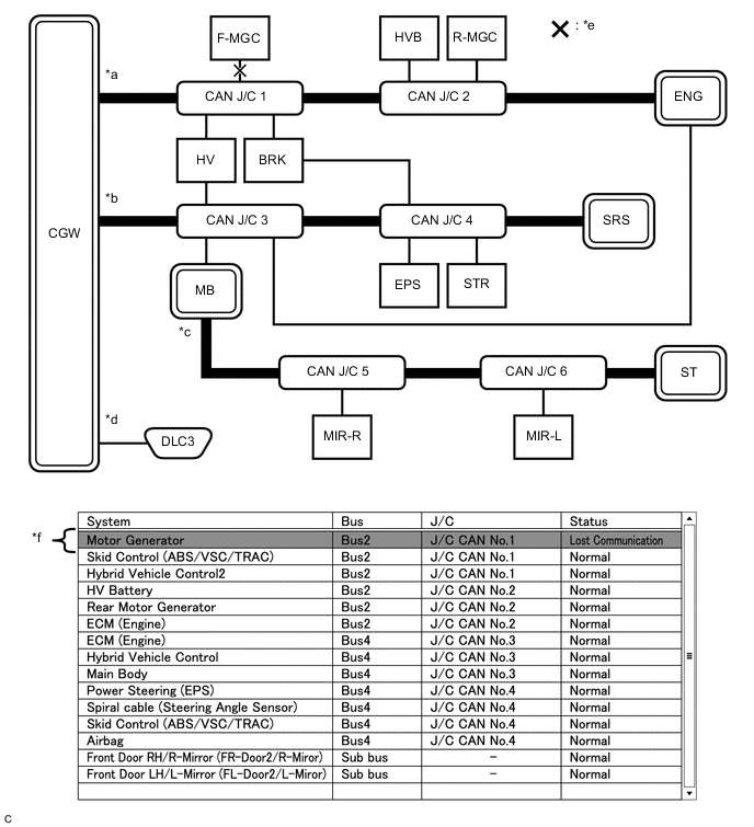
*a Bus 2 *b Bus 4 *c Sub bus *d Diagnosis bus *e Location of malfunction *f Background color is red Tech Tips
The information displayed on the "Communication Bus Check" screen will be the same for an open in both wires of a branch line, an internal malfunction of an ECU or sensor or a malfunction in the power supplied to an ECU or sensor. In this example, the background color of the malfunctioning ECU or sensor will be red.
Details of Malfunction
-
Internal malfunction of F-MGC in Bus 2
-
Malfunction in the power supplied to F-MGC in Bus 2
*a Bus 2 *b Bus 4 *c Sub bus *d Diagnosis bus *e Location of malfunction *f Background color is red Tech Tips
The information displayed on the "Communication Bus Check" screen will be the same for an open in both wires of a branch line, an internal malfunction of an ECU or sensor or a malfunction in the power supplied to an ECU or sensor. In this example, the background color of the malfunctioning ECU or sensor will be red.
Details of Malfunction Open in both wires of the branch line connected to ENG in Bus 4 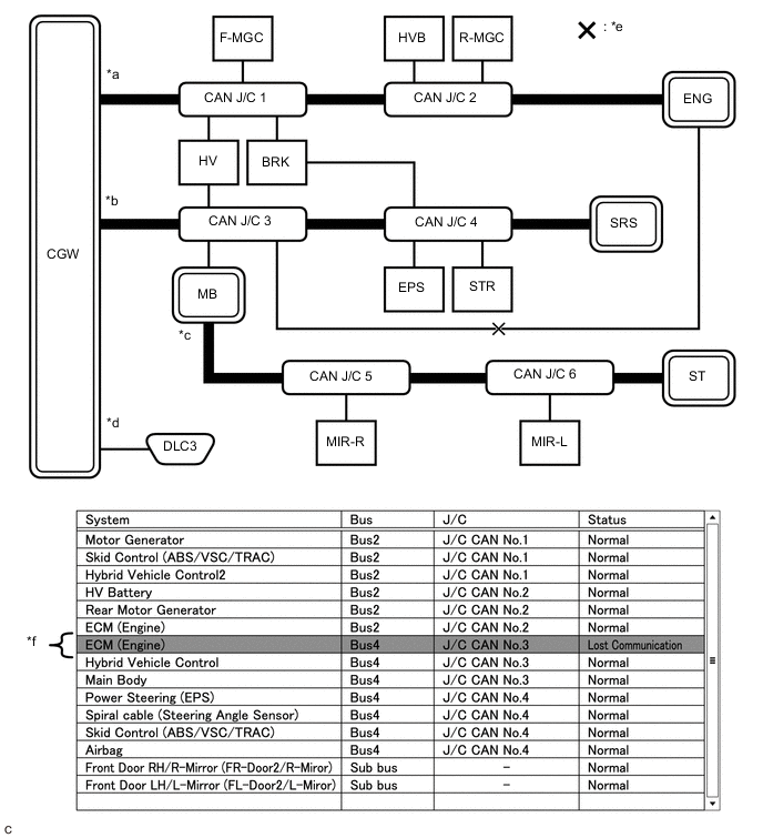
*a Bus 2 *b Bus 4 *c Sub bus *d Diagnosis bus *e Location of malfunction *f Background color is red Tech Tips
-
The malfunction in Bus 4 will not affect the other buses.
-
Due to the malfunction, although ENG is communicating normally with CGW via Bus 2, it is not communicating with CGW via Bus 4. Consequently, it will be displayed as not communicating in Bus 4.
-
-
Problem Symptom Pattern D
Details of Malfunction
-
Internal malfunction of the CGW
-
Malfunction in the power supplied to the CGW
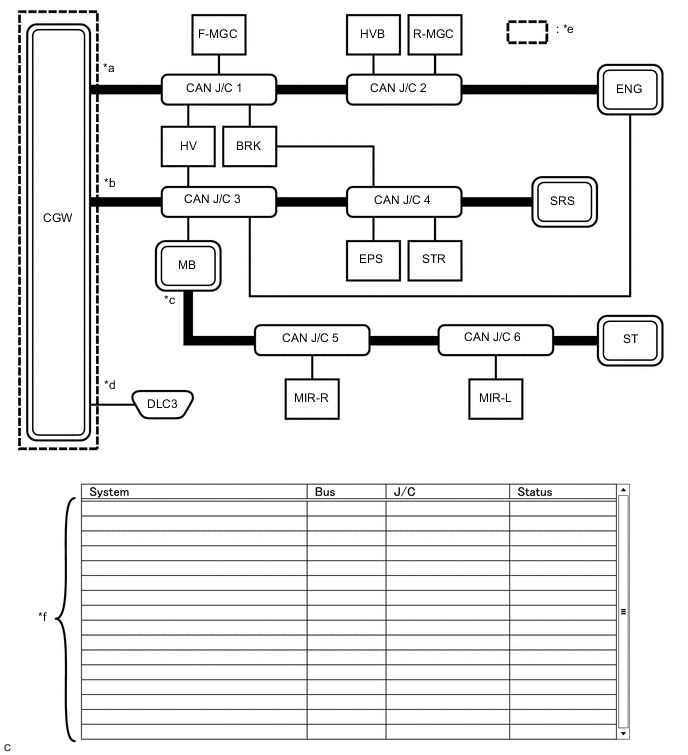
*a Bus 2 *b Bus 4 *c Sub bus *d Diagnosis bus *e Location of malfunction *f Not displayed Tech Tips
When there is no communication between the GTS and the vehicle, no ECUs or sensors will be displayed.
Details of Malfunction Open in both wires of the branch lines in the diagnosis bus 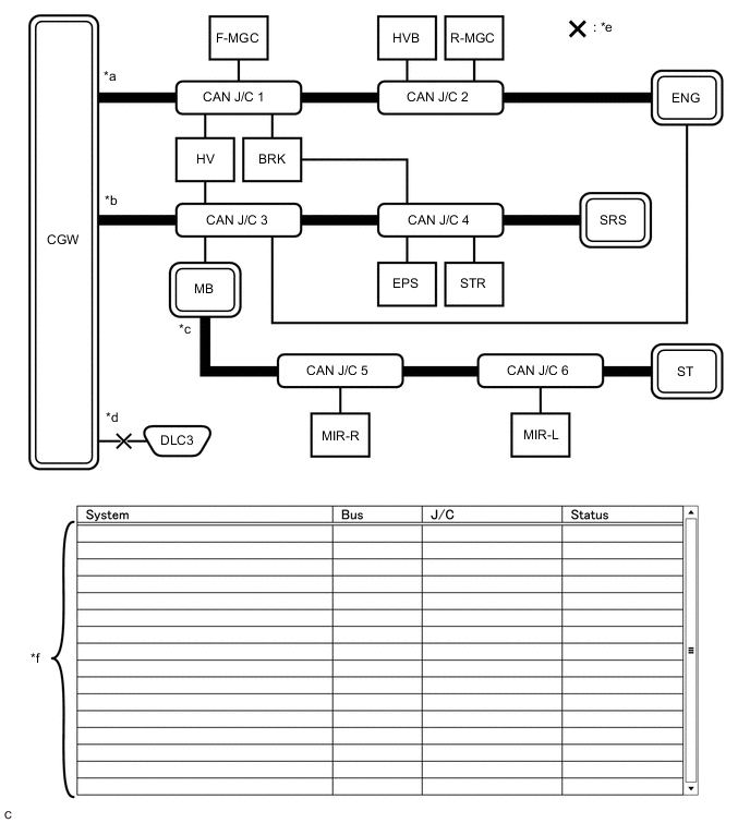
*a Bus 2 *b Bus 4 *c Sub bus *d Diagnosis bus *e Location of malfunction *f Not displayed Tech Tips
When there is no communication between the GTS and the vehicle, no ECUs or sensors will be displayed.
-
-
Problem Symptom Pattern E
Details of Malfunction
-
Internal malfunction of BRK
-
Malfunction in the power supplied to BRK
*a Bus 2 *b Bus 4 *c Sub bus *d Diagnosis bus *e Location of malfunction *f Background color is red Tech Tips
The information displayed on the "Communication Bus Check" screen will be the same for an internal malfunction of an ECU or sensor, or a malfunction in the power supplied to an ECU or sensor.
Due to the malfunction, BRK is not communicating with the CGW via both Bus 2 and Bus 4. Consequently, the background color of BRK will be red for both Bus 2 and Bus 4.
-
-
Problem Symptom Pattern F
Details of Malfunction
-
Open in a wire of the branch line connected to HV in Bus 4
-
Internal malfunction of HV in Bus 4
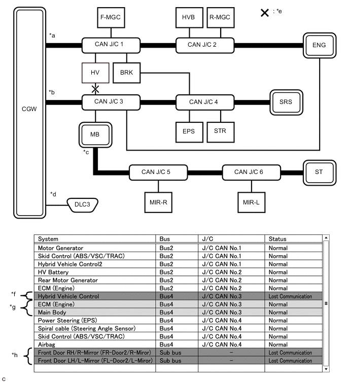
*a Bus 2 *b Bus 4 *c Sub bus *d Diagnosis bus *e Location of malfunction *f Background color is red *g Background color intermittently becomes yellow or red *h Not displayed or background color is yellow or red Tech Tips
-
In the "Communication Bus check" screen shown in the illustration, electrical noise in the CAN bus caused by an open in a wire in the branch line connected to HV interferes with the communication of MB causing unstable communication. Also, since MB is a gateway function equipped ECU, communication of ECUs connected to its respective sub bus will also be unstable.
-
In the "Communication Bus Check" screen shown in the illustration, because the background color of HV is red, it is suspected that HV is the most likely cause of the malfunction. Therefore, it is suspected that HV is not communicating.
-
-
Problem Symptom Pattern G
Details of Malfunction
-
Open in both wires of the branch line connected to MB in Bus 4
-
Internal malfunction of MB in Bus 4
-
Malfunction in the power supplied to MB in Bus 4
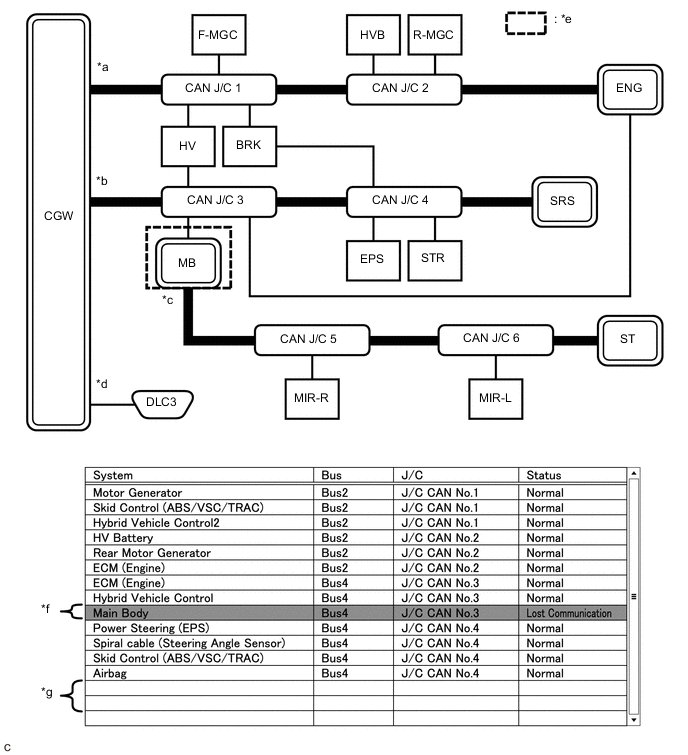
*a Bus 2 *b Bus 4 *c Sub bus *d Diagnosis bus *e Location of malfunction *f Background color is red *g Not displayed - - Tech Tips
-
If there is a communication malfunction in a gateway function equipped ECU, ECUs connected to its respective sub bus will also be affected and will not be displayed.
-
In the "Communication Bus Check" screen shown in the illustration, MB is a gateway function equipped ECU. Therefore, MB is suspected as not communicating.
-
-
Problem Symptoms Pattern H
Details of Malfunction
-
Internal malfunction of MIR-L in the sub bus
-
Malfunction in the power supplied to MIR-L in the sub bus
*a Bus 2 *b Bus 4 *c Sub bus *d Diagnosis bus *e Location of malfunction *f Background color is red Tech Tips
-
The malfunction in the sub bus will not affect the other buses.
-
When a gateway function equipped ECU memorizes ECUs and sensors connected to its respective sub bus and there is a communication malfunction in one of the ECUs or sensors, the background color of the ECU or sensor will change to red and the ECU or sensor will remain displayed.
-
The information displayed on the "Communication Bus Check" screen will be the same for an open in both wires of a branch line, an internal malfunction of an ECU or sensor or a malfunction in the power supplied to an ECU or sensor.
Details of Malfunction Open in both wires of the branch line connected to MIR-L in the sub bus 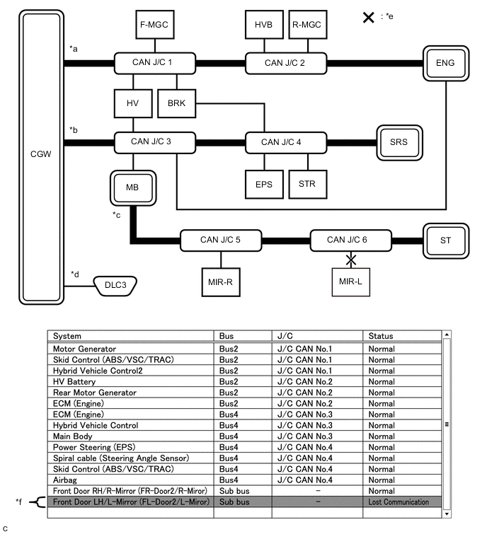
*a Bus 2 *b Bus 4 *c Sub bus *d Diagnosis bus *e Location of malfunction *f Background color is red Tech Tips
-
The malfunction in the sub bus will not affect the other buses.
-
When a gateway function equipped ECU memorizes ECUs and sensors connected to its respective sub bus and there is a communication malfunction in one of the ECUs or sensors, the background color of the ECU or sensor will change to red and the ECU or sensor will remain displayed.
-
The information displayed on the "Communication Bus Check" screen will be the same for an open in both wires of a branch line, an internal malfunction of an ECU or sensor or a malfunction in the power supplied to an ECU or sensor.
-
-
Problem Symptom Pattern I
Details of Malfunction Open in both wires of the main bus line in the sub bus 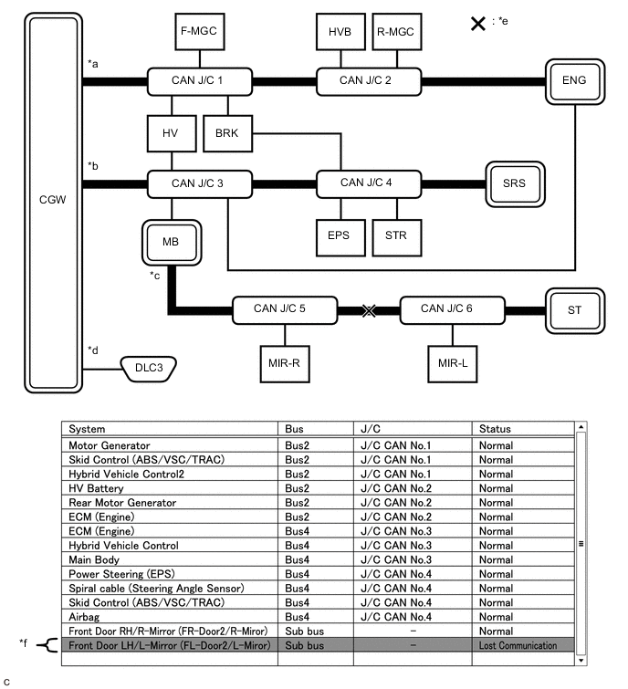
*a Bus 2 *b Bus 4 *c Sub bus *d Diagnosis bus *e Location of malfunction *f Background color is red Tech Tips
Due to the malfunction, ECUs or sensors farther from the sub bus monitoring ECU (gateway function equipped ECU) than the open in the wires will be displayed as not communicating and their background color will be red.
-
-
How to Use "Communication Bus check (Detail)" Screen in Inspection
-
If the CAN communication system is currently normal but has communication stop history, determine the malfunctioning part using Communication Bus Check (Detail) as follows:
Note
-
The following CAN bus wiring diagram or communication bus check screen is provided only as an example. This wiring diagram or screen differs from the actual one for this vehicle.
-
The Lost Communication Time column displays the longest period of time in seconds that the central gateway ECU (network gateway ECU) detected a communication stop in the respective ECU or sensor.
-
The Lost Communication Trip column displays the trip in which the central gateway ECU (network gateway ECU) detected the longest communication stop in the respective ECU or sensor.
-
When using the combo box, it may be possible to select a sub bus from the drop down list that does not have any connected ECUs or sensors. This is not a malfunction and occurs when there is no optional device connected to a sub bus which is monitored by a sub bus monitoring ECU (gateway function equipped ECU).
-
In the drop down list, all sub buses applicable to the model are displayed (e.g. LIN communication sub buses are also displayed). For information on sub buses necessary to diagnose CAN communication system, refer to the System Diagram.
Tech Tips
-
If the CAN communication system is currently malfunctioning, it is recommended to use Communication Bus Check rather than Communication Bus Check (Detail) for determining the suspected area.
-
The communication error history of ECUs or sensors which have communication error history can be displayed on the "Communication Bus Check (Detail)" screen.
-
Lost Communication Time and Lost Communication Trip are only displayed for the central bus.
-
Lost Communication Time and Lost Communication Trip are not displayed for sub buses.
-
-
If there is an ECU or sensor displayed with a red background on the "Communication Bus Check (Detail)" screen to indicate that it was not communicating, it is suspected that the ECU or sensor was not communicating.
Details of Malfunction Past malfunction in the wire harness or power supplied to F-MGC in Bus 2 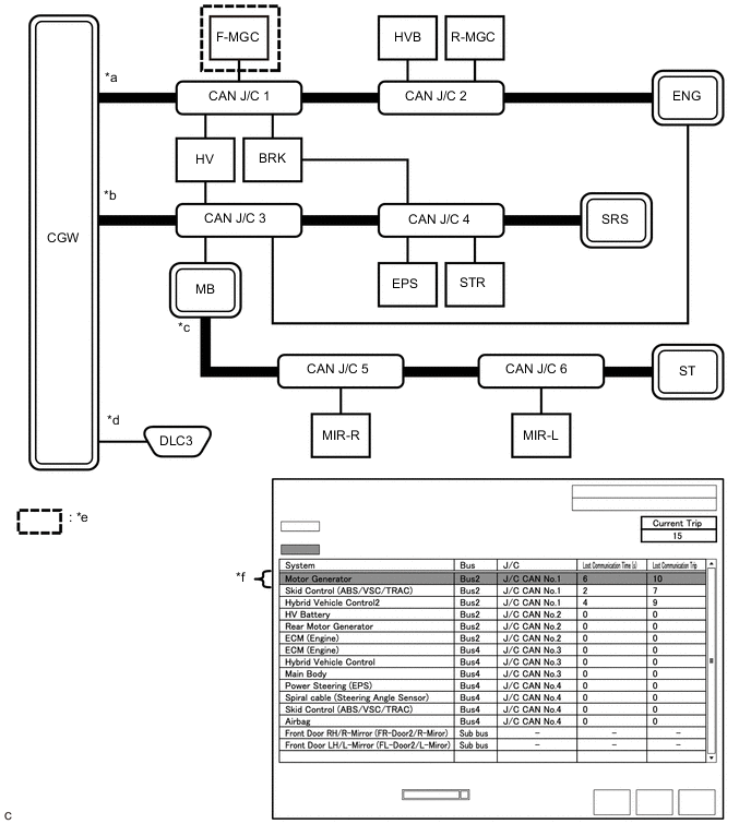
*a Bus 2 *b Bus 4 *c Sub bus *d Diagnosis bus *e Location of malfunction *f Background color is red Description of "Communication Bus Check (Detail)" Screen Bus Type Background Color Connection Status Bus White Either of the following:
-
Communication has been normal.
-
Lost Communication Time is below 6 seconds.
Red Lost Communication Time is 6 seconds or more. Not displayed Either of the following:
-
The central gateway ECU (network gateway ECU) has an internal malfunction or cannot communicate with the GTS.*1
-
No ECUs or sensors are connected to the bus.*2
Sub bus White Lost Communication Time is displayed as "-". Not displayed Either of the following:
-
The gateway function equipped ECU cannot communicate with the central gateway ECU.*3
-
No ECUs or sensors are connected to the sub bus.*4
Tech Tips
-
Check the values of Lost Communication Trip and Current Trip for the ECUs or sensors that have a red background color.
-
If the values of Lost Communication Trip and Current Trip are the same for an ECU or sensor, the ECU or sensor is currently not communicating. In this case, it is recommended to use Communication Bus Check rather than Communication Bus Check (Detail) for determining the suspected area.
-
In the "Communication Bus Check (Detail)" screen shown in the illustration, F-MGC had a communication malfunction in the 10th trip. Thus, it is suspected that F-MGC was not communicating.
-
*1: When the central gateway ECU (network gateway ECU) has an internal malfunction or cannot communicate with the GTS, the name of buses, sub buses, ECUs and sensors will not be displayed.
-
*2: When no ECUs or sensors are connected to a bus, the message "There is no system found on the communication Bus." will be displayed.
-
*3: When a gateway function equipped ECU cannot communicate with the central gateway ECU (network gateway ECU), the name of sub buses and ECUs or sensors connected to the sub bus will not be displayed.
-
*4: When no ECUs or sensors are connected to the sub bus, the message "There is no system found on the communication Bus." will be displayed.
-
-
-
DTC TABLE BY ECU
Tech Tips
-
In the CAN communication system, the CAN communication DTCs of each ECU can be displayed using the GTS.
-
If CAN communication system DTCs are output, the malfunction cannot be determined only by the DTCs. Perform troubleshooting according to How to Proceed with Troubleshooting.
-
If there is a malfunction currently, DTCs can be checked by performing steps in the DTC check procedure.
-
ECM / GTS Display "Engine"
Tech Tips
DTC communication uses the CAN communication system.
Powertrain > Engine > Trouble CodesDTC No. Detection Item DTC Detection Condition DTC Detection Precondition DTC Check Procedure Warning Displayed DTC Storage Method Indication in Meter Multi-information Display U011087 Lost Communication with Drive Motor Control Module "A" Missing Message Communication stop occurs between the inverter with converter assembly and ECM continuously for approximately 6 seconds or more. All conditions are met:
-
2 seconds or more elapse after the power switch is on (IG).
-
The power source voltage of the ECM is 9.5 V or higher.
Turn the power switch on (IG) and wait at least approximately 8 seconds. MIL (Check engine warning light) illuminates. - DTC is stored until it is cleared using the Techstream. U029387 Lost Communication with Hybrid Powertrain Control Module Missing Message Communication stop occurs between the hybrid vehicle control ECU assembly and ECM continuously for approximately 1 second or more. All conditions are met:
-
1 second or more elapse after the power switch is on (IG).
-
The power source voltage of the ECM is 10 V or higher.
Turn the power switch on (IG) and wait at least approximately 2 seconds. MIL (Check engine warning light) illuminates. - DTC is stored until it is cleared using the Techstream. U117587 Lost Communication with HV Battery(Powertrain Bus) Missing Message Communication stop occurs between the battery ECU assembly and ECM continuously for approximately 51 seconds or more. All conditions are met:
-
1 second or more elapse after the power switch is on (IG).
-
The power source voltage of the ECM is 9.5 V or higher.
Turn the power switch on (IG) and wait at least approximately 52 seconds. MIL (Check engine warning light) illuminates. - DTC is stored until it is cleared using the Techstream. -
-
Hybrid Vehicle Control ECU Assembly / GTS Display "Hybrid Control"
Tech Tips
DTC communication uses the CAN communication system.
Powertrain > Hybrid Control > Trouble CodesDTC No. Detection Item DTC Detection Condition DTC Detection Precondition DTC Check Procedure Warning Displayed DTC Storage Method Indication in Meter Multi-information Display U010087 Lost Communication with ECM/PCM "A" Missing Message Communication stop occurs between the hybrid vehicle control ECU assembly and ECM continuously for approximately 1 second or more. All conditions are met:
-
1 second or more elapse after the power switch is on (IG).
-
The power source voltage of the hybrid vehicle control ECU assembly is 9.5 V or higher.
Turn the power switch on (IG) and wait at least approximately 2 seconds. MIL (Check engine warning light) illuminates. - DTC is stored until it is cleared using the GTS. U010387* Lost Communication with Gear Shift Control Module "A" (Hybrid/EV Battery Local Bus) Missing Message Communication stop occurs between the hybrid vehicle control ECU assembly and shift control ECU continuously for 1 seconds or more. All conditions are met:
-
1 second or more elapse after the power switch is on (IG).
-
The power source voltage of the hybrid vehicle control ECU assembly is 9.5 V or higher.
Turn the power switch on (IG) and wait at least approximately 2 seconds. MIL (Check engine warning light) illuminates. - DTC is stored until it is cleared using the GTS. U011087 Lost Communication with Drive Motor Control Module "A" Missing Message Communication stop occurs between the hybrid vehicle control ECU assembly and inverter with converter assembly continuously for approximately 1 seconds or more. All conditions are met:
-
1 second or more elapse after the power switch is on (IG).
-
The power source voltage of the hybrid vehicle control ECU assembly is 9.5 V or higher.
Turn the power switch on (IG) and wait at least approximately 2 seconds. - - DTC is stored until it is cleared using the GTS. U011187* Lost Communication with Hybrid/EV Battery Energy Control Module "A" Missing Message Either of the following conditions is met:
-
Communication stop occurs between the hybrid vehicle control ECU assembly and battery ECU assembly continuously for approximately 1 seconds or more.
-
Communication stop occurs between the hybrid vehicle control ECU assembly and battery ECU assembly continuously for approximately 2 seconds or more.
All conditions are met:
-
1 second or more elapse after a power source mode change is detected (+B changes from off to on (IG) , on (ACC) changes between on (IG) and off, or on (IG) changes between on (IG) and off).
-
The power source voltage of the hybrid vehicle control ECU assembly is 9.5 V or higher.
Turn the power switch on (IG) and wait at least approximately 3 seconds. MIL (Check engine warning light) illuminates. - DTC is stored until it is cleared using the GTS. U012987 Lost Communication with Brake System Control Module Missing Message Communication stop occurs between the hybrid vehicle control ECU assembly and skid control ECU assembly continuously for approximately 3 seconds or more. All conditions are met:
-
2 seconds or more elapse after the power switch is on (IG).
-
The power source voltage of the hybrid vehicle control ECU assembly is 9.5 V or higher.
Turn the power switch on (IG) and wait at least approximately 5 seconds. - - DTC is stored until it is cleared using the GTS. U014087 Lost Communication with Body Control Module Missing Message Communication stop occurs between the hybrid vehicle control ECU assembly and main body ECU (multiplex network body ECU) continuously for approximately 4 seconds or more. All conditions are met:
-
3 seconds or more elapse after the power switch is on (IG).
-
The power source voltage of the hybrid vehicle control ECU assembly is 9.5 V or higher.
Turn the power switch on (IG) and wait at least approximately 7 seconds. - - DTC is stored until it is cleared using the GTS. U015187 Lost Communication with Restraints Control Module Missing Message Communication stop occurs between the hybrid vehicle control ECU assembly and yaw rate sensor continuously for 11 seconds or more. All conditions are met:
-
11 seconds or more elapse after the power switch is on (IG).
-
The power source voltage of the hybrid vehicle control ECU assembly is 9.5 V or higher.
Turn the power switch on (IG) and wait at least 22 seconds. - - DTC is stored until it is cleared using the GTS. U016487 Lost Communication with HVAC Control Module Missing Message Communication stop occurs between the hybrid vehicle control ECU assembly and air conditioning amplifier assembly continuously for approximately 11 seconds or more. All conditions are met:
-
3 seconds or more elapse after the power switch is on (IG).
-
The power source voltage of the hybrid vehicle control ECU assembly is 9.5 V or higher.
Turn the power switch on (IG) and wait at least approximately 14 seconds. - - DTC is stored until it is cleared using the GTS. U029387 Lost Communication with Hybrid/EV Powertrain Control Module Missing Message Communication stop occurs between the hybrid vehicle control ECU assembly and skid control ECU assembly continuously for approximately 1 seconds or more. All conditions are met:
-
3 seconds or more elapse after the power switch is on (IG).
-
The power source voltage of the hybrid vehicle control ECU assembly is 10 V or higher.
Turn the power switch on (IG) and wait at least approximately 14 seconds. - - DTC is stored until it is cleared using the GTS. U042481 HVAC Control Module to Hybrid Powertrain Control Module Invalid Serial Data Received The hybrid vehicle control ECU assembly receives the malfunction signal from the air conditioning amplifier assembly continuously for approximately 4 seconds or more. All conditions are met:
-
Approximately 4 seconds or more elapse after the power switch is on (IG).
-
The power source voltage of the hybrid vehicle control ECU assembly is 9.5 V or higher.
Turn the power switch on (IG) and wait at least approximately 8 seconds. - - DTC is stored until it is cleared using the GTS. U110787 Lost Communication with Power Management Module Missing Message Communication stop occurs between the hybrid vehicle control ECU assembly and certification ECU (smart key ECU assembly) continuously for approximately 4 seconds or more. All conditions are met:
-
3 seconds or more elapse after the power switch is on (IG).
-
The power source voltage of the hybrid vehicle control ECU assembly is 9.5 V or higher.
Turn the power switch on (IG) and wait at least approximately 7 seconds. - - DTC is stored until it is cleared using the GTS. U117087 Lost Communication with Brake System Control Module (Secondary CAN Line) Missing Message Communication stop occurs between the hybrid vehicle control ECU assembly and skid control ECU assembly continuously for approximately 3 seconds or more. All conditions are met:
-
2 seconds or more elapse after the power switch is on (IG).
-
The power source voltage of the
Turn the power switch on (IG) and wait at least approximately 5 seconds. - - DTC is stored until it is cleared using the GTS. U117587 Lost Communication with Hybrid/EV Battery Energy Control Module "A" (Powertrain Bus) Missing Message Communication stop occurs between the hybrid vehicle control ECU assembly and battery ECU assembly continuously for approximately 51 seconds or more. All conditions are met:
-
1 second or more elapse after the power switch is on (IG).
-
The power source voltage of the hybrid vehicle control ECU assembly is 9.5 V or higher.
Turn the power switch on (IG) and wait at least approximately 52 seconds. MIL (Check engine warning light) illuminates. - DTC is stored until it is cleared using the GTS. U117687 Lost Communication with Gear Shift Control Module "A" (Powertrain Bus) Missing Message Communication stop occurs between the hybrid vehicle control ECU assembly and shift control ECU continuously for approximately 2 seconds or more. All conditions are met:
-
1 second or more elapse after the power switch is on (IG).
-
The power source voltage of the hybrid vehicle control ECU assembly is 9.5 V or higher.
Turn the power switch on (IG) and wait at least approximately 3 seconds. - - DTC is stored until it is cleared using the GTS. *: Refer to Hybrid Control System
-
-
Shift Control ECU / GTS Display "Hybrid Control"
Tech Tips
DTC communication uses the CAN communication system.
Powertrain > Hybrid Control > Trouble CodesDTC No. Detection Item DTC Detection Condition DTC Detection Precondition DTC Check Procedure Warning Displayed DTC Storage Method Indication in Meter Multi-information Display U010387* Lost Communication with Gear Shift Control Module "A" (Hybrid/EV Battery Local Bus) Missing Message Communication stop occurs between the hybrid vehicle control ECU assembly and shift control ECU continuously for 1 second or more. All conditions are met:
-
1 second or more elapse after the power switch is on (IG).
-
The power source voltage of the shift control ECU is 10 V or higher.
Turn the power switch on (IG) and wait at least 2 seconds. MIL (Check engine warning light) illuminates. - DTC is stored until it is cleared using the Techstream. U014000 Lost Communication with Cruise Control Module Missing Message Communication stop occurs between the shift control ECU and main body ECU (multiplex network body ECU) continuously for approximately 4 seconds or more. All conditions are met:
-
3 seconds or more elapse after the power switch is on (IG).
-
The power source voltage of the shift control ECU is 10 V or higher.
Turn the power switch on (IG) and wait at least approximately 7 seconds. - Displays messages on the multi-information display. DTC is stored until it is cleared using the Techstream. U029300 Lost Communication with Hybrid/EV Powertrain Control Module from Gear Shift Control Module "A" Either of the following conditions is met:
-
Communication stop occurs between the shift control ECU and hybrid vehicle control ECU assembly continuously for 1 second or more.
-
Communication stop occurs between the shift control ECU and hybrid vehicle control ECU assembly continuously for approximately 11 seconds or more.
All conditions are met:
-
3 seconds or more elapse after the power switch is on (IG).
-
The power source voltage of the shift control ECU is 10 V or higher.
Turn the power switch on (IG) and wait at least approximately 14 seconds. - Displays messages on the multi-information display. DTC is stored until it is cleared using the Techstream. U110700 Lost Communication with Power Management Module (Gear Shift Control Module "A") Communication stop occurs between the shift control ECU and certification ECU (smart key ECU assembly) continuously for approximately 4 seconds or more. All conditions are met:
-
3 seconds or more elapse after the power switch is on (IG).
-
The power source voltage of the shift control ECU is 10 V or higher.
Turn the power switch on (IG) and wait at least approximately 7 seconds. - Displays messages on the multi-information display. DTC is stored until it is cleared using the Techstream. U117000 Lost Communication with Brake System Control Module (Gear Shift Control Module "A") Communication stop occurs between the shift control ECU and skid control ECU assembly continuously for approximately 3 seconds or more. All conditions are met:
-
3 seconds or more elapse after the power switch is on (IG).
-
The power source voltage of the shift control ECU is 10 V or higher.
Turn the power switch on (IG) and wait at least approximately 6 seconds. - Displays messages on the multi-information display. DTC is stored until it is cleared using the Techstream. *: Refer to Electronic Shift Lever System
for 2WD: Click here
for 4WD: Click here
-
-
Sub-battery with Control Assembly / GTS Display "Sub Battery Module"
Tech Tips
DTC communication uses the CAN communication system.
Body Electrical > Sub Battery Module > Trouble CodesDTC No. Detection Item DTC Detection Condition DTC Detection Precondition DTC Check Procedure Warning Displayed DTC Storage Method Indication in Meter Multi-information Display U0100 Lost Communication with ECM/PCM "A" Either of the following conditions is met:
-
Communication stop occurs between the sub-battery with control assembly and hybrid vehicle control ECU assembly continuously for approximately 2 seconds or more.
-
DLC error is detected in data received from the hybrid vehicle control ECU assembly.
-
Checksum error is detected in data received from the hybrid vehicle control ECU assembly.
All conditions are met:
-
3 seconds or more elapse after the power switch is on (IG).
-
The power source voltage of the sub-battery with control assembly is 10 V or higher.
-
After turning the power switch on (IG), the sub-battery with control assembly receives a data from the hybrid vehicle control ECU assembly or ECM 1 time or more
Turn the power switch on (IG) and wait at least approximately 5 seconds. - - DTC is stored until it is cleared using the Techstream. U0129 Lost Communication with Brake System Control Module Either of the following conditions is met:
-
Communication stop occurs between the sub-battery with control assembly and skid control ECU assembly continuously for approximately 1 second or more.
-
DLC error is detected in data received from the skid control ECU assembly.
-
Checksum error is detected in data received from the skid control ECU assembly.
All conditions are met:
-
3 seconds or more elapse after the power switch is on (IG).
-
The power source voltage of the sub-battery with control assembly is 10 V or higher.
Turn the power switch on (IG) and wait at least approximately 4 seconds. - - DTC is stored until it is cleared using the Techstream. U0164 Lost Communication with HVAC Control Module When conditions 1 and 2 are continuously met:
-
After the power switch is turned from off to on (IG), sub-battery with control assembly receive malfunction data from the air conditioning amplifier assembly or hybrid vehicle control ECU assembly 1 time or more.
-
Either of the following conditions is met:
-
Communication stop occurs between the sub-battery with control assembly and air conditioning amplifier assembly continuously for 10 seconds or more.
-
DLC error is detected in data received from the air conditioning amplifier assembly.
All conditions are met:
-
3 seconds or more elapse after the power switch is on (IG).
-
The power source voltage of the sub-battery with control assembly is 10 V or higher.
Turn the power switch on (IG) and wait at least 13 seconds. - - DTC is stored until it is cleared using the Techstream. U0293 Lost Communication with Hybrid Powertrain Control Module When conditions 1 and 2 are continuously met:
-
After the power switch is turned from off to on (IG), sub-battery with control assembly receive data from the hybrid vehicle control ECU assembly 1 time or more.
-
Either of the following conditions is met:
-
Communication stop occurs between the sub-battery with control assembly and hybrid vehicle control ECU assembly continuously for approximately 1 second or more.
-
DLC error is detected in data received from the hybrid vehicle control ECU assembly.
-
Checksum error is detected in data received from the hybrid vehicle control ECU assembly.
All conditions are met:
-
3 seconds or more elapse after the power switch is on (IG).
-
The power source voltage of the sub-battery with control assembly is 10 V or higher.
-
After turning the power switch on (IG), the sub-battery with control assembly receives a data from the hybrid vehicle control ECU assembly assembly or ECM 1 time or more.
Turn the power switch on (IG) and wait at least approximately 4 seconds. - - DTC is stored until it is cleared using the Techstream. U1107 Lost Communication with Power Management Module When conditions 1 and 2 are continuously met:
-
Communication stop occurs between the sub-battery with control assembly and certification ECU (smart key ECU assembly) continuously for approximately 3 seconds or more.
-
DLC error is detected in data received from the certification ECU (smart key ECU assembly).
All conditions are met:
-
3 seconds or more elapse after the power switch is on (IG).
-
The power source voltage of the sub-battery with control assembly is 10 V or higher.
Turn the power switch on (IG) and wait at least approximately 6 seconds. - - DTC is stored until it is cleared using the Techstream. -
-
Battery ECU Assembly / GTS Display "HV Battery"
Tech Tips
DTC communication uses the CAN communication system.
Powertrain > HV Battery > Trouble CodesDTC No. Detection Item DTC Detection Condition DTC Detection Precondition DTC Check Procedure Warning Displayed DTC Storage Method Indication in Meter Multi-information Display U010087 Lost Communication with ECM/PCM "A" Missing Message Communication stop occurs between the battery ECU assembly and ECM continuously for approximately 2 seconds or more. All conditions are met:
-
1 second or more elapse after the power switch is on (IG).
-
The power source voltage of the battery ECU assembly is 9.6 V or higher.
Turn the power switch on (IG) and wait at least approximately 3 seconds.
-
MIL (Check engine warning light) illuminates.
-
Master warning light illuminates
- Up to 3 trips are stored after the system returns to normal U029387 Lost Communication with Hybrid/EV Powertrain Control Module Missing Message Communication stop occurs between the battery ECU assembly and hybrid vehicle control ECU assembly continuously for 1 seconds or more. All conditions are met:
-
1 second or more elapse after the power switch is on (IG).
-
The power source voltage of the battery ECU assembly is 9.6 V or higher.
Turn the power switch on (IG) and wait at least 2 seconds.
-
MIL (Check engine warning light) illuminates.
-
Master warning light illuminates
- Up to 3 trips are stored after the system returns to normal U115087* Lost Communication with Hybrid Powertrain Control Module (Hybrid/EV Battery Local Bus) Missing Message Communication stop occurs between the battery ECU assembly and hybrid vehicle control ECU assembly continuously for 1 seconds or more. All conditions are met:
-
1 second or more elapse after the IGCT is on (IG).
-
The power source voltage of the battery ECU assembly is 9.6 V or higher.
Turn the IGCT on (IG) and wait for at least 2 seconds
-
MIL (Check engine warning light) illuminates.
-
Master warning light illuminates
- Up to 3 trips are stored after the system returns to normal *: Refer to Hybrid Battery Control System
-
-
Inverter with Converter Assembly / GTS Display "Motor Generator"
Tech Tips
DTC communication uses the CAN communication system.
Powertrain > Motor Generator > Trouble CodesDTC No. Detection Item DTC Detection Condition DTC Detection Precondition DTC Check Procedure Warning Displayed DTC Storage Method Indication in Meter Multi-information Display U010087 Lost Communication With ECM/PCM "A" Missing Message Communication stop occurs between the inverter with converter assembly and ECM continuously for 1 second or more. All conditions are met:
-
1 second or more elapse after the power switch is on (IG).
-
The power source voltage of the inverter with converter assembly is 9.5 V or higher.
Turn the power switch on (IG) and wait at least 3 seconds.
-
MIL (Check engine warning light) illuminates.
-
Master warning light illuminates.
- DTC is stored until it is cleared using the Techstream. U029387 Lost Communication With Hybrid Powertrain Control Module Missing Message Communication stop occurs between the inverter with converter assembly and hybrid vehicle control ECU assembly continuously for 1 second or more. All conditions are met:
-
1 second or more elapse after the power switch is on (IG).
-
The power source voltage of the inverter with converter assembly is 9.5 V or higher.
Turn the power switch on (IG) and wait at least 3 seconds.
-
MIL (Check engine warning light) illuminates.
-
Master warning light illuminates.
- DTC is stored until it is cleared using the Techstream. U117087 Lost Communication With Brake System Control Module(ch2) Missing Message Communication stop occurs between the inverter with converter assembly and skid control ECU assembly continuously for approximately 3 seconds or more. All conditions are met:
-
2 seconds or more elapse after the power switch is on (IG).
-
The power source voltage of the inverter with converter assembly is 9.5 V or higher.
Turn the power switch on (IG) and wait at least approximately 7 seconds. Master warning light illuminates. - DTC is stored until it is cleared using the Techstream. -
-
Skid Control ECU Assembly / GTS Display "ABS/VSC/TRC"
Tech Tips
DTC communication uses the CAN communication system.
Chassis > ABS/VSC/TRC > Trouble CodesDTC No. Detection Item DTC Detection Condition DTC Detection Precondition DTC Check Procedure Warning Displayed DTC Storage Method Indication in Meter Multi-information Display U0073 Control Module Communication Bus Off Either of the following conditions is met:
-
Communication stop occurs at least 10 times in 5 seconds.
-
Communication stop occurs between the skid control ECU assembly and yaw rate sensor, steering sensor, front steering control ECU, rear steering control ECUcontinuously for 1 second or more.
-
The following conditions occur at least 10 times within 60 seconds:
-
Communication stop occurs between the skid control ECU assembly and yaw rate sensor at least 1 time within 5 seconds.
-
Communication stop occurs between the skid control ECU assembly and steering sensor at least 1 time within 5 seconds.
-
Communication stop occurs between the skid control ECU assembly and front steering control ECU at least 1 time within 5 seconds.
-
Communication stop occurs between the skid control ECU assembly and rear steering control ECU at least 1 time within 5 seconds.
-
The bus turns off consecutively.
All conditions are met:
-
3 seconds or more elapse after the power switch is on (IG).
-
The power source voltage of the skid control ECU assembly is 10 V or higher.
Turn the power switch on (IG) and wait at least 63 seconds.
-
ABS warning light illuminates.
-
Slip indicator light illuminates.
-
Brake warning light illuminates.
Displays messages on the multi-information display. DTC is stored until it is cleared using the Techstream. U0110 Lost Communication With Drive Motor Control Module "A" Either of the following conditions is met:
-
Communication stop occurs between the skid control ECU assembly and hybrid vehicle control ECU assembly continuously for 2 seconds or more.
-
Communication stop occurs between the skid control ECU assembly and hybrid vehicle control ECU assembly 1 time or more within 5 seconds at least 10 times.
All conditions are met:
-
3 seconds or more elapse after the power switch is on (IG).
-
The power source voltage of the skid control ECU assembly is 10 V or higher.
Turn the power switch on (IG) and wait at least 53 seconds.
-
Brake warning light illuminates.
-
Slip indicator light illuminates.
-
Brake hold indicator light blinks.
- DTC is stored until it is cleared using the Techstream. U0120 Lost Communication With Starter / Generator Control Module Communication stop occurs between the skid control ECU assembly and certification ECU (smart key ECU assembly) continuously for 3 seconds or more. All conditions are met:
-
3 seconds or more elapse after the power switch is on (IG).
-
The power source voltage of the skid control ECU assembly is 10 V or higher.
Turn the power switch on (IG) and wait at least 6 seconds. Brake warning light illuminates. - DTC is stored until it is cleared using the Techstream. U0124 Lost Communication With Lateral Acceleration Sensor Module Either of the following conditions is met:
-
Communication stop occurs between the skid control ECU assembly and yaw rate sensor continuously for 1 second or more.
-
Communication stop occurs between the skid control ECU assembly and yaw rate sensor 1 time or more within 5 seconds and at least 10 times for 60 seconds.
All conditions are met:
-
3 seconds or more elapse after the power switch is on (IG).
-
The power source voltage of the skid control ECU assembly is 10 V or higher.
Turn the power switch on (IG) and wait at least 63 seconds.
-
ABS warning light illuminates.
-
Slip indicator light illuminates.
-
Brake hold indicator light blinks.
-
Brake warning light illuminates.
Displays messages on the multi-information display. DTC is stored until it is cleared using the Techstream. U0126 Lost Communication With Steering Angle Sensor Module Either of the following conditions is met:
-
Communication stop occurs between the skid control ECU assembly and steering sensor continuously for 1 second or more.
-
Communication stop occurs between the skid control ECU assembly and steering sensor 1 time or more within 5 seconds and at least 10 times for 60 seconds.
All conditions are met:
-
3 seconds or more elapse after the power switch is on (IG).
-
The power source voltage of the skid control ECU assembly is 10 V or higher.
Turn the power switch on (IG) and wait at least 63 seconds.
-
Slip indicator light illuminates.
-
Brake hold indicator light blinks.
- DTC is stored until it is cleared using the Techstream. U0128 Lost Communication With EPB Module Communication stop occurs between the skid control ECU assembly and parking assist ECU continuously for 1 second or more. All conditions are met:
-
3 seconds or more elapse after the power switch is on (IG).
-
The power source voltage of the skid control ECU assembly is 10 V or higher.
Turn the power switch on (IG) and wait at least 4 seconds. Brake hold indicator light blinks. - DTC is stored until it is cleared using the Techstream. U0130 Lost Communication With Steering Effort Control Module Either of the following conditions is met:
-
Communication stop occurs between the skid control ECU assembly and front steering control ECU continuously for 1 second or more.
-
Communication stop occurs between the skid control ECU assembly and front steering control ECU 1 time or more within 5 seconds and at least 10 times for 60 seconds
All conditions are met:
-
3 seconds or more elapse after the power switch is on (IG).
-
The power source voltage of the skid control ECU assembly is 10 V or higher.
Turn the power switch on (IG) and wait at least 63 seconds.
-
Slip indicator light illuminates.
-
Brake hold indicator light blinks.
- DTC is stored until it is cleared using the Techstream. U0134 Lost Communication With DRS Module Either of the following conditions is met:
-
Communication stop occurs between the skid control ECU assembly and rear steering control ECU continuously for 1 second or more.
-
Communication stop occurs between the skid control ECU assembly and rear steering control ECU 1 time or more within 5 seconds and at least 10 times for 60 seconds.
All conditions are met:
-
3 seconds or more elapse after the power switch is on (IG).
-
The power source voltage of the skid control ECU assembly is 10 V or higher.
Turn the power switch on (IG) and wait at least 63 seconds.
-
Slip indicator light illuminates.
-
Brake hold indicator light blinks.
- DTC is stored until it is cleared using the Techstream. U0151 Lost Communication With Restraints Control Module Communication stop occurs between the skid control ECU assembly and airbag ECU assembly continuously for 5 seconds or more. All conditions are met:
-
3 seconds or more elapse after the power switch is on (IG).
-
The power source voltage of the skid control ECU assembly is 10 V or higher.
Turn the power switch on (IG) and wait at least 8 seconds. - Displays messages on the multi-information display. DTC is stored until it is cleared using the Techstream. U0293 Lost Communication With Hybrid Vehicle Control System Either of the following conditions is met:
-
Communication stop occurs between the skid control ECU assembly and hybrid vehicle control ECU assembly continuously for 2 seconds or more.
-
Communication stop occurs between the skid control ECU assembly and hybrid vehicle control ECU assembly 1 time or more within 5 seconds at least 10 times.
All conditions are met:
-
3 seconds or more elapse after the power switch is on (IG).
-
The power source voltage of the skid control ECU assembly is 10 V or higher.
Turn the power switch on (IG) and wait at least 53 seconds.
-
Brake warning light illuminates.
-
Slip indicator light illuminates.
-
Brake hold indicator light blinks.
Displays messages on the multi-information display. DTC is stored until it is cleared using the Techstream. -
-
Parking Brake ECU Assembly / GTS Display "Electric Parking Brake"
Tech Tips
DTC communication uses the CAN communication system.
Chassis > Electric Parking Brake > Trouble CodesDTC No. Detection Item DTC Detection Condition DTC Detection Precondition DTC Check Procedure Warning Displayed DTC Storage Method Indication in Meter Multi-information Display U0073 Control Module Communication Bus OFF The parking brake ECU assembly cannot send and receive data (The bus is off) for approximately 2 seconds or more. All conditions are met:
-
The power switch is on (IG).
-
The power source voltage of the parking assist ECU is 10 V or higher.
Turn the power switch on (IG) and wait at least approximately 2 seconds. Parking brake warning light illuminates. - DTC is stored until it is cleared using the Techstream. U0100 Lost Communication With ECM/PCM "A" Either of the following conditions is met:
-
Communication stop occurs between the parking assist ECU and ECM continuously for 1 second or more.
-
Communication stop occurs between the parking assist ECU and ECM continuously for 10 seconds or more.
All conditions are met:
-
2 seconds or more elapse after the power switch is on (IG).
-
The power source voltage of the parking assist ECU is 10 V or higher.
-
The vehicle speed is 15 km/h (9 mph) or more.
Drive the vehicle for 12 seconds or more at a speed of 15 km/h (9 mph) or more. Parking brake warning light illuminates. - DTC is stored until it is cleared using the Techstream. U0124 Lost Communication With Lateral Acceleration Sensor Module Communication stop occurs between the parking assist ECU and yaw rate sensor continuously for 1 second or more. All conditions are met:
-
2 seconds or more elapse after the power switch is on (IG).
-
The power source voltage of the parking assist ECU is 10 V or higher.
-
The vehicle speed is 15 km/h (9 mph) or more.
Drive the vehicle for 3 seconds or more at a speed of 15 km/h (9 mph) or more. Parking brake warning light illuminates. - DTC is stored until it is cleared using the Techstream. U0129 Lost Communication With Brake System Control Module Communication stop occurs between the parking assist ECU and skid control ECU assembly continuously for 1 second or more. All conditions are met:
-
2 seconds or more elapse after the power switch is on (IG).
-
The power source voltage of the parking assist ECU is 10 V or higher.
Turn the power switch on (IG) and wait at least 3 seconds. Parking brake warning light illuminates. - DTC is stored until it is cleared using the Techstream. U0293 Lost Communication With Hybrid Vehicle Control System Either of the following conditions is met:
-
Communication stop occurs between the parking assist ECU and hybrid vehicle control ECU assembly continuously for 1 second or more.
-
Communication stop occurs between the parking assist ECU and hybrid vehicle control ECU assembly continuously for 10 seconds or more.
All conditions are met:
-
2 seconds or more elapse after the power switch is on (IG).
-
The power source voltage of the parking assist ECU is 10 V or higher.
-
The vehicle speed is 15 km/h (9 mph) or more.
Drive the vehicle for 12 seconds or more at a speed of 15 km/h (9 mph) or more. Parking brake warning light illuminates. - DTC is stored until it is cleared using the Techstream. -
-
Rack and Pinion Power Steering Gear Assembly / GTS Display "EMPS"
Tech Tips
DTC communication uses the CAN communication system.
Chassis > EMPS > Trouble CodesDTC Detection Item DTC Detection Condition DTC Detection Precondition DTC Check Procedure Warning Displayed DTC Storage Method Indication in Meter Multi-information Display U0126 Lost Communication with Steering Angle Sensor Module Communication stop occurs between the rack and pinion power steering gear assembly and steering sensor continuously for approximately 6 seconds or more. All conditions are met:
-
3 seconds or more elapse after the power switch is on (IG).
-
The power source voltage of the rack and pinion power steering gear assembly is 9 V or higher.
Turn the power switch on (IG) and wait at least approximately 9 seconds. - - DTC remains stored only while malfunction is occurring. U0129 Lost Communication with Brake System Control Module Communication stop occurs between the rack and pinion power steering gear assembly and skid control ECU assembly continuously for approximately 3 seconds or more. All conditions are met:
-
3 seconds or more elapse after the power switch is on (IG).
-
The power source voltage of the rack and pinion power steering gear assembly is 9 V or higher.
Turn the power switch on (IG) and wait at least approximately 6 seconds. EPS warning light illuminates. - DTC remains stored only while malfunction is occurring. U0130 Lost Communication with Steering Effort Control Module Communication stop occurs between the rack and pinion power steering gear assembly and front steering control ECU continuously for approximately 2 seconds or more. All conditions are met:
-
3 seconds or more elapse after the power switch is on (IG).
-
The power source voltage of the rack and pinion power steering gear assembly is 9 V or higher.
Turn the power switch on (IG) and wait at least approximately 5 seconds. - - DTC remains stored only while malfunction is occurring. U0134 Lost Communication with DRS Module Communication stop occurs between the rack and pinion power steering gear assembly and rear steering control ECU continuously for approximately 2 seconds or more. All conditions are met:
-
3 seconds or more elapse after the power switch is on (IG).
-
rack and pinion power steering gear assembly is 9 V or higher.
Turn the power switch on (IG) and wait at least approximately 5 seconds. - - DTC remains stored only while malfunction is occurring. U023A Lost Communication with Front Camera Module
-
Communication stop occurs between the rack and pinion power steering gear assembly and forward recognition camera continuously for approximately 2 seconds or more.*1
-
Communication stop occurs between the rack and pinion power steering gear assembly and object recognition camera continuously for approximately 2 seconds or more.*2
All conditions are met:
-
3 seconds or more elapse after the power switch is on (IG).
-
The power source voltage of the rack and pinion power steering gear assembly is 9 V or higher.
Turn the power switch on (IG) and wait at least approximately 5 seconds. - - DTC remains stored only while malfunction is occurring. U0293 Lost Communication with Hybrid Control Module Communication stop occurs between the rack and pinion power steering gear assembly and hybrid vehicle control ECU assembly continuously for 5 minutes or more. All conditions are met:
-
3 seconds or more elapse after the power switch is on (IG).
-
The power source voltage of the rack and pinion power steering gear assembly is 9 V or higher.
-
The vehicle speed is 20 km/h (12 mph) or more.
Drive the vehicle for approximately 5 minutes or more at a speed of 20 km/h (12 mph) or more. - - DTC remains stored only while malfunction is occurring. Communication stop occurs between the rack and pinion power steering gear assembly and hybrid vehicle control ECU assembly continuously for approximately 3 seconds or more. All conditions are met:
-
3 seconds or more elapse after the power switch is on (IG).
-
The power source voltage of the rack and pinion power steering gear assembly is 9 V or higher.
Turn the power switch on (IG) and wait at least approximately 6 seconds. - - DTC remains stored only while malfunction is occurring. U1104 Lost Communication with Driving Support ECU
-
Communication stop occurs between the rack and pinion power steering gear assembly and forward recognition camera continuously for approximately 2 seconds or more.*1
-
Communication stop occurs between the rack and pinion power steering gear assembly and object recognition camera continuously for approximately 2 seconds or more.*2
All conditions are met:
-
3 seconds or more elapse after the power switch is on (IG).
-
The power source voltage of the rack and pinion power steering gear assembly is 9 V or higher.
Turn the power switch on (IG) and wait at least approximately 5 seconds. - - DTC remains stored only while malfunction is occurring. *1: w/ Pre-collision System (for Mono Camera Type)
*2: w/ Pre-collision System (for Stereo Camera Type)
-
-
Front Steering Control ECU / GTS Display "VGRS" (w/ Variable Gear Ratio Steering System)
Tech Tips
DTC communication uses the CAN communication system.
Chassis > VGRS > Trouble CodesDTC No. Detection Item DTC Detection Condition DTC Detection Precondition DTC Check Procedure Warning Displayed DTC Storage Method Indication in Meter Multi-information Display U0101 Lost Communication with TCM Communication stop occurs between the front steering control ECU and hybrid vehicle control ECU assembly continuously for 12 seconds or more. All conditions are met:
-
1 second or more elapse after the power switch is on (IG).
-
The power source voltage of the front steering control ECU is 10 to 16V.
Turn the power switch on (IG) and wait at least 13 seconds. Master warning light illuminates Displays messages on the multi-information display. DTC is stored until it is cleared using the Techstream. U0125 Lost Communication with Yaw Rate Sensor Module Communication stop occurs between the front steering control ECU and yaw rate sensor continuously for 12 seconds or more. All conditions are met:
-
1 second or more elapse after the power switch is on (IG).
-
The power source voltage of the front steering control ECU is 10 to 16V.
Turn the power switch on (IG) and wait at least 13 seconds. Master warning light illuminates Displays messages on the multi-information display. DTC is stored until it is cleared using the Techstream. U0126 Lost Communication with Steering Angle Sensor Module Communication stop occurs between the front steering control ECU and steering sensor continuously for 3 seconds or more. All conditions are met:
-
1 second or more elapse after the power switch is on (IG).
-
The power source voltage of the front steering control ECU is 10 to 16V.
Turn the power switch on (IG) and wait at least 4 seconds. Master warning light illuminates Displays messages on the multi-information display. DTC is stored until it is cleared using the Techstream. U0129 Lost Communication with Brake System Control Module Either of the following conditions is met:
-
Communication stop occurs between the front steering control ECU and skid control ECU assembly continuously for 3 seconds or more.
-
Communication stop occurs between the front steering control ECU and skid control ECU assembly continuously for 12 seconds or more.
All conditions are met:
-
2 seconds or more elapse after the power switch is on (IG).
-
The power source voltage of the front steering control ECU is 10 to 16V.
Turn the power switch on (IG) and wait at least 14 seconds. Master warning light illuminates Displays messages on the multi-information display. DTC is stored until it is cleared using the Techstream. U0131 Lost Communication with Power Steering Control Module Communication stop occurs between the front steering control ECU and rack and pinion power steering gear assembly continuously for 3 seconds or more. All conditions are met:
-
1 second or more elapse after the power switch is on (IG).
-
The power source voltage of the front steering control ECU is 10 to 16V.
Turn the power switch on (IG) and wait at least 4 seconds. Master warning light illuminates Displays messages on the multi-information display. DTC is stored until it is cleared using the Techstream. U0293 Lost Communication with Hybrid Vehicle Control System Communication stop occurs between the front steering control ECU and hybrid vehicle control ECU assembly continuously for 3 seconds or more. All conditions are met:
-
1 second or more elapse after the power switch is on (IG).
-
The power source voltage of the front steering control ECU is 10 to 16V.
Turn the power switch on (IG) and wait at least 4 seconds. Master warning light illuminates Displays messages on the multi-information display. DTC is stored until it is cleared using the Techstream. -
-
Rear Steering Control ECU / GTS Display "DRS" (w/ Dynamic Rear Steering System)
Tech Tips
DTC communication uses the CAN communication system.
Chassis > DRS > Trouble CodesDTC No. Detection Item DTC Detection Condition DTC Detection Precondition DTC Check Procedure Warning Displayed DTC Storage Method Indication in Meter Multi-information Display U0129 Lost Communication with Brake System Control Module Communication stop occurs between the rear steering control ECU and skid control ECU assembly continuously for 3 seconds or more. All conditions are met:
-
2 seconds or more elapse after the power switch is on (IG).
-
The power source voltage of the rear steering control ECU is 10 to 16V.
Turn the power switch on (IG) and wait at least 5 seconds. Master warning light illuminates Displays messages on the multi-information display. DTC is stored until it is cleared using the Techstream. U0130 Lost Communication with Steering Effort Control Module Communication stop occurs between the rear steering control ECU and front steering control ECU continuously for 3 seconds or more. All conditions are met:
-
1 second or more elapse after the power switch is on (IG).
-
The power source voltage of the rear steering control ECU is 10 to 16V.
Turn the power switch on (IG) and wait at least 4 seconds. Master warning light illuminates Displays messages on the multi-information display. DTC is stored until it is cleared using the Techstream. U0293 Lost Communication with Hybrid Vehicle Control System Communication stop occurs between the rear steering control ECU and hybrid vehicle control ECU assembly continuously for 3 seconds or more. All conditions are met:
-
1 second or more elapse after the power switch is on (IG).
-
The power source voltage of the rear steering control ECU is 10 to 16V.
-
The vehicle speed is 20 km/h (12 mph) or more.
Drive the vehicle for 4 seconds or more at a speed of 20 km/h (12 mph) or more. Master warning light illuminates Displays messages on the multi-information display. DTC is stored until it is cleared using the Techstream. -
-
Absorber Control ECU / GTS Display "Adaptive Variable Suspension System"
Tech Tips
DTC communication uses the CAN communication system.
Chassis > Adaptive Variable Suspension System > Trouble CodesDTC No. Detection Item DTC Detection Condition DTC Detection Precondition DTC Check Procedure Warning Displayed DTC Storage Method Indication in Meter Multi-information Display U0101 Lost Communication with TCM Communication stop occurs between the absorber control ECU and hybrid vehicle control ECU assembly continuously for 6 seconds or more. All conditions are met:
-
1 second or more elapse after the power switch is on (IG).
-
The power source voltage of the absorber control ECU is 10 V or higher.
-
The vehicle speed is 30 km/h (19 mph) or more.
Drive the vehicle for 7 seconds or more at a speed of 30 km/h (19 mph) or more. - - DTC is stored until it is cleared using the Techstream. U0122 Lost Communication with Vehicle Dynamics Control Module Communication stop occurs between the absorber control ECU and skid control ECU assembly continuously for 3 seconds or more. All conditions are met:
-
2 seconds or more elapse after the power switch is on (IG).
-
The power source voltage of the absorber control ECU is 10 V or higher.
Turn the power switch on (IG) and wait at least 5 seconds. - - DTC is stored until it is cleared using the Techstream. U0124 Lost Communication with Lateral Acceleration Sensor Module Communication stop occurs between the absorber control ECU and yaw rate sensor continuously for 3 seconds or more. All conditions are met:
-
1 second or more elapse after the power switch is on (IG).
-
The power source voltage of the absorber control ECU is 10 V or higher.
-
The vehicle speed is 7 km/h (4 mph) or more.
Drive the vehicle for 4 seconds or more at a speed of 7 km/h (4 mph) or more. - - DTC is stored until it is cleared using the Techstream. U0126 Lost Communication with Steering Angle Sensor Module Communication stop occurs between the absorber control ECU and steering sensor continuously for 3 seconds or more. All conditions are met:
-
1 second or more elapse after the power switch is on (IG).
-
The power source voltage of the absorber control ECU is 10 V or higher.
Turn the power switch on (IG) and wait at least 4 seconds. - - DTC is stored until it is cleared using the Techstream. U0130 Lost Communication with VGRS Communication stop occurs between the absorber control ECU and front steering control ECU continuously for 3 seconds or more. All conditions are met:
-
5 seconds or more elapse after the power switch is on (IG).
-
The power source voltage of the absorber control ECU is 10 V or higher. absorber control ECU is 10 V or higher.
-
The absorber control ECU receives a VGRS available signal from the steering sensor.
Turn the power switch on (IG) and wait at least 8 seconds. - - DTC is stored until it is cleared using the Techstream. U0293 Lost Communication with Hybrid Vehicle Control System Communication stop occurs between the absorber control ECU and hybrid vehicle control ECU assembly continuously for 3 seconds or more. All conditions are met:
-
1 second or more elapse after the power switch is on (IG).
-
The power source voltage of the absorber control ECU is 10 V or higher. absorber control ECU is 10 V or higher.
-
The vehicle speed is 30 km/h (19 mph) or more.
Drive the vehicle for 4 seconds or more at a speed of 30 km/h (19 mph) or more. - - DTC is stored until it is cleared using the Techstream. U114C Lost Communication with Suspension Control Module 1 Communication stop occurs between the absorber control ECU and suspension control ECU continuously for 4 seconds or more. All conditions are met:
-
5 seconds or more elapse after the power switch is on (IG).
-
absorber control ECU is 10 V or higher.
Turn the power switch on (IG) and wait at least 9 seconds. - - DTC is stored until it is cleared using the Techstream. -
-
Suspension Control ECU / GTS display "Air suspension" (w/ Air Suspension System)
Tech Tips
DTC communication uses the CAN communication system.
Chassis > Air suspension > Trouble CodesDTC No. Detection Item DTC Detection Condition DTC Detection Precondition DTC Check Procedure Warning Displayed DTC Storage Method Indication in Meter Multi-information Display U010087 Lost Communication with ECM/PCM "A" Missing Message Communication stop occurs between the suspension control ECU and ECM continuously for 3 seconds or more. All conditions are met:
-
1 second or more elapse after the power switch is on (IG).
-
The power source voltage of the suspension control ECU is 10 V or higher.
-
The vehicle speed is 30 km/h (19 mph) or more.
Drive the vehicle for 7 seconds or more at a speed of 30 km/h (19 mph) or more. - - DTC is stored until it is cleared using the Techstream. U010187 Lost Communication with TCM Missing Message Communication stop occurs between the suspension control ECU and hybrid vehicle control ECU assembly continuously for 6 seconds or more. All conditions are met:
-
1 second or more elapse after the power switch is on (IG).
-
The power source voltage of the suspension control ECU is 10 V or higher.
-
The vehicle speed is 30 km/h (19 mph) or more.
Drive the vehicle for 7 seconds or more at a speed of 30 km/h (19 mph) or more. - - DTC is stored until it is cleared using the Techstream. U012587 Lost Communication with Multi-Axis Acceleration Sensor Module Missing Message Communication stop occurs between the suspension control ECU and yaw rate sensor continuously for 3 seconds or more. All conditions are met:
-
1 second or more elapse after the power switch is on (IG).
-
The power source voltage of the suspension control ECU is 10 V or higher.
-
The vehicle speed is 30 km/h (19 mph) or more.
Drive the vehicle for 4 seconds or more at a speed of 30 km/h (19 mph) or more. - - DTC is stored until it is cleared using the Techstream. U012687 Lost Communication with Steering Angle Sensor Module Missing Message Communication stop occurs between the suspension control ECU and steering sensor continuously for 3 seconds or more. All conditions are met:
-
1 second or more elapse after the power switch is on (IG).
-
The power source voltage of the suspension control ECU is 10 V or higher.
Turn the power switch on (IG) and wait at least 4 seconds. - - DTC is stored until it is cleared using the Techstream. U012987 Lost Communication with Brake System Control Module Missing Message Communication stop occurs between the suspension control ECU and skid control ECU assembly continuously for 3 seconds or more. All conditions are met:
-
2 seconds or more elapse after the power switch is on (IG).
-
The power source voltage of the suspension control ECU is 10 V or higher.
Turn the power switch on (IG) and wait at least 5 seconds. - - DTC is stored until it is cleared using the Techstream. U013087 Lost Communication with Steering Effort Control Module Missing Message Communication stop occurs between the suspension control ECU and front steering control ECU continuously for 3 seconds or more. All conditions are met:
-
1 second or more elapse after the power switch is on (IG).
-
The power source voltage of the suspension control ECU is 10 V or higher.
Turn the power switch on (IG) and wait at least 4 seconds. - - DTC is stored until it is cleared using the Techstream. U014087 Lost Communication with Body Control Module Missing Message Communication stop occurs between the suspension control ECU and main body ECU (multiplex network body ECU) continuously for 10 seconds or more. All conditions are met:
-
1 second or more elapse after a power source mode change is detected (+B changes from off to on (IG) , on (ACC) changes between on (IG) and off, or on (IG) changes between on (IG) and off).
-
The power source voltage of the suspension control ECU is 10 V or higher.
Turn the power switch on (IG) and wait at least 11 seconds. - - DTC is stored until it is cleared using the Techstream. U015587 Lost Communication with Instrument Panel Cluster (IPC) Control Module Missing Message Communication stop occurs between the suspension control ECU and combination meter assembly continuously for 10 seconds or more. All conditions are met:
-
1 second or more elapse after the power switch is on (IG).
-
The power source voltage of the suspension control ECU is 10 V or higher.
-
The vehicle speed is 30 km/h (19 mph) or more.
Drive the vehicle for 4 seconds or more at a speed of 30 km/h (19 mph) or more. - - DTC is stored until it is cleared using the Techstream. U029387 Lost Communication with Hybrid Powertrain Control Module Missing Message Communication stop occurs between the suspension control ECU and hybrid vehicle control ECU assembly continuously for 3 seconds or more. All conditions are met:
-
1 second or more elapse after the power switch is on (IG).
-
The power source voltage of the suspension control ECU is 10 V or higher.
-
The vehicle speed is 30 km/h (19 mph) or more.
Drive the vehicle for 4 seconds or more at a speed of 30 km/h (19 mph) or more. - - DTC is stored until it is cleared using the Techstream. -
-
Hybrid Vehicle Control ECU Assembly / GTS Display "Cruise Control" (w/ Cruise Control System)
Tech Tips
DTC communication uses the CAN communication system.
Powertrain > Cruise Control > Trouble CodesDTC No. Detection Item DTC Detection Condition DTC Detection Precondition DTC Check Procedure Warning Displayed DTC Storage Method Indication in Meter Multi-information Display U012287 Lost Communication with Vehicle Dynamics Control Module Missing Message Communication stop occurs between the hybrid vehicle control ECU assembly and skid control ECU assembly continuously for approximately 3 seconds or more. All conditions are met:
-
The power switch is on (IG).
-
The cruise control system is in operation.
Turn the cruise control system on and wait for approximately 3 seconds or more - Displays messages on the multi-information display. DTC is stored until it is cleared using the GTS. -
-
Hybrid Vehicle Control ECU Assembly / GTS Display "Radar Cruise1" (w/ Dynamic Radar Cruise Control System)
Tech Tips
DTC communication uses the CAN communication system.
Powertrain > Cruise Control > Trouble CodesDTC No. Detection Item DTC Detection Condition DTC Detection Precondition DTC Check Procedure Warning Displayed DTC Storage Method Indication in Meter Multi-information Display U010487 Lost Communication with Cruise Control Module Missing Message Communication stop occurs between the driving support ECU assembly and hybrid vehicle control ECU assembly, driving support ECU assembly and skid control ECU assembly or driving support ECU assembly and millimeter wave radar sensor assembly continuously for approximately 1 second or more. All conditions are met:
-
The power switch is on (IG).
-
The dynamic radar cruise control system is in operation.
Turn the dynamic radar cruise control system on and wait for approximately 1 second or more. - Displays messages on the multi-information display. DTC is stored until it is cleared using the GTS. U012287 Lost Communication with Vehicle Dynamics Control Module Missing Message Communication stop occurs between the hybrid vehicle control ECU assembly and skid control ECU assembly continuously for approximately 3 seconds or more. All conditions are met:
-
The power switch is on (IG).
-
The dynamic radar cruise control system is in operation.
Turn the dynamic radar cruise control system on and wait for approximately 3 seconds or more - Displays messages on the multi-information display. DTC is stored until it is cleared using the GTS. U029387 Lost Communication with Hybrid Powertrain Control Module Missing Message Communication stop occurs between the skid control ECU assembly and hybrid vehicle control ECU assembly continuously for 1 seconds or more. All conditions are met:
-
The power switch is on (IG).
-
The dynamic radar cruise control system is in operation.
Turn the dynamic radar cruise control system on and wait for 1 second or more. - Displays messages on the multi-information display. DTC is stored until it is cleared using the GTS. -
-
Driving Support ECU Assembly / GTS Display "Radar Cruise 2" (w/ Pre-collision System [for Mono Camera Type])
Tech Tips
DTC communication uses the CAN communication system.
Powertrain > Radar Cruise2 > Trouble CodesDTC No. Detection Item DTC Detection Condition DTC Detection Precondition DTC Check Procedure Warning Displayed DTC Storage Method Indication in Meter Multi-information Display U0125 Lost Communication with Yaw Rate Sensor Module Communication stop occurs between the driving support ECU assembly and yaw rate sensor continuously for approximately 1 seconds or more. All conditions are met:
-
The dynamic radar cruise control system is in operation.
-
Vehicle speed is 5 km/h (3 mph) or more.*1
-
Vehicle speed is 36 km/h (22 mph) or more.*2
-
3 seconds or more elapse after the power switch is on (IG).
-
The power source voltage of the driving support ECU assembly is 10 V or higher.
-
With the dynamic radar cruise operating, drive the vehicle for approximately 4 seconds or more at a speed of 5 km/h (3 mph) or higher.*1
-
With the dynamic radar cruise operating, drive the vehicle for approximately 4 seconds or more at a speed of 36 km/h (22 mph) or higher.*2
- Displays messages on the multi-information display. DTC is stored until it is cleared using the GTS. U0126 Lost Communication with Steering Angle Sensor Module Communication stop occurs between the driving support ECU assembly and steering sensor continuously for approximately 1 seconds or more. All conditions are met:
-
The dynamic radar cruise control system is in operation.
-
Vehicle speed is 5 km/h (3 mph) or more.*1
-
Vehicle speed is 36 km/h (22 mph) or more.*2
-
1 second or more elapse after the power switch is on (IG).
-
The power source voltage of the driving support ECU assembly is 10 V or higher.
-
With the dynamic radar cruise operating, drive the vehicle for approximately 2 seconds or more at a speed of 5 km/h (3 mph) or higher.*1
-
With the dynamic radar cruise operating, drive the vehicle for approximately 2 seconds or more at a speed of 36 km/h (22 mph) or higher.*2
- Displays messages on the multi-information display. DTC is stored until it is cleared using the GTS. U0129 Lost Communication with Brake System Control Module Communication stop occurs between the driving support ECU assembly and skid control ECU assembly continuously for approximately 2 seconds or more. All conditions are met:
-
The dynamic radar cruise control system is in operation.
-
Vehicle speed is 5 km/h (3 mph) or more.*1
-
Vehicle speed is 36 km/h (22 mph) or more.*2
-
2 seconds or more elapse after the power switch is on (IG).
-
The power source voltage of the driving support ECU assembly is 10 V or higher.
-
With the dynamic radar cruise operating, drive the vehicle for approximately 4 seconds or more at a speed of 5 km/h (3 mph) or higher.*1
-
With the dynamic radar cruise operating, drive the vehicle for approximately 4 seconds or more at a speed of 36 km/h (22 mph) or higher.*2
- Displays messages on the multi-information display. DTC is stored until it is cleared using the GTS. U0235 Lost Communication with Cruise Control Front Distance Range Sensor Communication data between the driving support ECU assembly and millimeter wave radar sensor assembly is continuously abnormal for approximately 2 seconds or more. All conditions are met:
-
The dynamic radar cruise control system is in operation.
-
Vehicle speed is 5 km/h (3 mph) or more.*1
-
Vehicle speed is 36 km/h (22 mph) or more.*2
-
1 second or more elapse after the power switch is on (IG).
-
The power source voltage of the driving support ECU assembly is 10 V or higher.
-
With the dynamic radar cruise operating, drive the vehicle for approximately 3 seconds or more at a speed of 5 km/h (3 mph) or higher.*1
-
With the dynamic radar cruise operating, drive the vehicle for approximately 3 seconds or more at a speed of 36 km/h (22 mph) or higher.*2
- Displays messages on the multi-information display. DTC is stored until it is cleared using the GTS. U0293 Lost Communication with Hybrid Vehicle Control System Communication stop occurs between the driving support ECU assembly and hybrid vehicle control ECU assembly continuously for 1 second or more. All conditions are met:
-
The dynamic radar cruise control system is in operation.
-
Vehicle speed is 5 km/h (3 mph) or more.*1
-
Vehicle speed is 36 km/h (22 mph) or more.*2
-
1 second or more elapse after the power switch is on (IG).
-
The power source voltage of the driving support ECU assembly is 10 V or higher.
-
With the dynamic radar cruise operating, drive the vehicle for approximately 2 seconds or more at a speed of 5 km/h (3 mph) or higher.*1
-
With the dynamic radar cruise operating, drive the vehicle for approximately 2 seconds or more at a speed of 36 km/h (22 mph) or higher.*2
- Displays messages on the multi-information display. DTC is stored until it is cleared using the GTS. U1104*3 Lost Communication with Driving Support ECU Communication stop occurs between the driving support ECU assembly and millimeter wave radar sensor assembly continuously for approximately 1 seconds or more. All conditions are met:
-
The dynamic radar cruise control system is in operation.
-
Vehicle speed is 5 km/h (3 mph) or more.*1
-
Vehicle speed is 36 km/h (22 mph) or more.*2
-
1 second or more elapse after the power switch is on (IG).
-
The power source voltage of the driving support ECU assembly is 10 V or higher.
-
With the dynamic radar cruise operating, drive the vehicle for approximately 2 seconds or more at a speed of 5 km/h (3 mph) or higher.*1
-
With the dynamic radar cruise operating, drive the vehicle for approximately 2 seconds or more at a speed of 36 km/h (22 mph) or higher.*2
- Displays messages on the multi-information display. DTC is stored until it is cleared using the GTS. *1: w/ Full Speed Range Flowing Function
*2: w/o Full Speed Range Flowing Function
*3: Refer to Dynamic Radar Cruise Control System
-
-
Driving Support ECU Assembly / GTS Display "Radar Cruise 2" (w/ Pre-collision System [for Stereo Camera Type])
Tech Tips
DTC communication uses the CAN communication system.
Powertrain > Radar Cruise2 > Trouble CodesDTC No. Detection Item DTC Detection Condition DTC Detection Precondition DTC Check Procedure Warning Displayed DTC Storage Method Indication in Meter Multi-information Display U012587 Lost Communication with Multi-axis Acceleration Sensor Module Missing Message Communication stop occurs between the driving support ECU assembly and yaw rate sensor continuously for approximately 1 seconds or more. All conditions are met:
-
The dynamic radar cruise control system is in
-
The vehicle speed is 5 km/h (3 mph) or more.
-
3 seconds or more elapse after the power switch is on (IG).
-
The power source voltage of the driving support ECU assembly is 10 V or higher.
With the dynamic radar cruise operating, drive the vehicle for approximately 4 seconds or more at a speed of 5 km/h (3 mph) or more. - Displays messages on the multi-information display. DTC is stored until it is cleared using the GTS. U012687 Lost Communication with Steering Angle Sensor Module Missing Message Communication stop occurs between the driving support ECU assembly and steering sensor continuously for approximately 1 seconds or more. All conditions are met:
-
The dynamic radar cruise control system is in
-
The vehicle speed is 5 km/h (3 mph) or more.
-
3 seconds or more elapse after the power switch is on (IG).
-
The power source voltage of the driving support ECU assembly is 10 V or higher.
With the dynamic radar cruise operating, drive the vehicle for approximately 2 seconds or more at a speed of 5 km/h (3 mph) or more. - Displays messages on the multi-information display. DTC is stored until it is cleared using the GTS. U012987 Lost Communication with Brake System Control Module Missing Message Communication stop occurs between the driving support ECU assembly and skid control ECU assembly continuously for approximately 2 seconds or more. All conditions are met:
-
The dynamic radar cruise control system is in
-
The vehicle speed is 5 km/h (3 mph) or more.
-
The power source voltage of the 3 seconds or more elapse after the power switch is on (IG).
-
driving support ECU assembly is 10 V or higher.
With the dynamic radar cruise operating, drive the vehicle for 4 seconds or more at a speed of 5 km/h (3 mph) or more. - Displays messages on the multi-information display. DTC is stored until it is cleared using the GTS. U015587 Lost Communication with Instrument Panel Cluster (IPC) Control Module Missing Message Communication stop occurs between the driving support ECU assembly and combination meter assembly continuously for approximately 5 seconds or more. All conditions are met:
-
The dynamic radar cruise control system is in
-
The vehicle speed is 5 km/h (3 mph) or more.
-
3 seconds or more elapse after the power switch is on (IG).
-
The power source voltage of the driving support ECU assembly is 10 V or higher.
With the dynamic radar cruise operating, drive the vehicle for approximately 10 seconds or more at a speed of 5 km/h (3 mph) or more. - Displays messages on the multi-information display. DTC is stored until it is cleared using the GTS. U016387 Lost Communication with Navigation Control Module Missing Message Communication stop occurs between the driving support ECU assembly and radio receiver assembly continuously for approximately 15 seconds or more. All conditions are met:
-
The dynamic radar cruise control system is in
-
The vehicle speed is 36 km/h (22 mph) or more.
-
60 seconds or more elapse after the power switch is on (IG).
-
The power source voltage of the driving support ECU assembly is 10 V or higher.
With the dynamic radar cruise operating, drive the vehicle for approximately 75 seconds or more at a speed of 36 km/h (22 mph) or more. - Displays messages on the multi-information display. DTC is stored until it is cleared using the GTS. U023587 Lost Communication with Cruise Control Front Distance Range Sensor Single Sensor or Center Missing Message Communication data between the driving support ECU assembly and millimeter wave radar sensor assembly is continuously abnormal for approximately 2 seconds or more. All conditions are met:
-
The dynamic radar cruise control system is in
-
The vehicle speed is 5 km/h (3 mph) or more.
-
3 seconds or more elapse after the power switch is on (IG).
-
The power source voltage of the driving support ECU assembly is 10 V or higher.
With the dynamic radar cruise operating, drive the vehicle for 5 seconds or more at a speed of 5 km/h (3 mph) or more. - Displays messages on the multi-information display. DTC is stored until it is cleared using the GTS. U023A87 Lost Communication with Image Processing Module "A" Missing Message Communication stop occurs between the millimeter wave radar sensor assembly and forward object camera continuously for approximately 2 seconds or more. All conditions are met:
-
The dynamic radar cruise control system is in
-
The vehicle speed is 5 km/h (3 mph) or more.
-
3 seconds or more elapse after the power switch is on (IG).
-
The power source voltage of the driving support ECU assembly is 10 V or higher.
With the dynamic radar cruise operating, drive the vehicle for approximately 5 seconds or more at a speed of 5 km/h (3 mph) or more. - Displays messages on the multi-information display. DTC is stored until it is cleared using the GTS. U029387 Lost Communication with Hybrid Vehicle Control System Communication stop occurs between the driving support ECU assembly and hybrid vehicle control ECU assembly continuously for approximately 1 second or more. All conditions are met:
-
The dynamic radar cruise control system is in
-
The vehicle speed is 5 km/h (3 mph) or more.
-
3 seconds or more elapse after the power switch is on (IG).
-
The power source voltage of the driving support ECU assembly is 10 V or higher.
With the dynamic radar cruise operating, drive the vehicle for approximately 4 seconds or more at a speed of 5 km/h (3 mph) or more. - Displays messages on the multi-information display. DTC is stored until it is cleared using the Techstream. -
-
Driving Support ECU Assembly / GTS Display "Pre-Collision 2" (w/ Pre-collision System [for Mono Camera Type])
Tech Tips
DTC communication uses the CAN communication system.
Body Electrical > Pre-Collision 2 > Trouble CodesDTC No. Detection Item DTC Detection Condition DTC Detection Precondition DTC Check Procedure Warning Displayed DTC Storage Method Indication in Meter Multi-information Display U0125 Lost Communication with Yaw Rate Sensor Module Communication stop occurs between the driving support ECU assembly and yaw rate sensor continuously for approximately 1 second or more. All conditions are met:
-
3 seconds or more elapse after the power switch is on (IG).
-
The power source voltage of the driving support ECU assembly is 10 V or higher.
Turn the power switch on (IG) and wait at least approximately 4 seconds. PCS warning light blinks. Displays messages on the multi-information display. DTC is stored until it is cleared using the GTS. U0126 Lost Communication with Steering Angle Sensor Module Communication stop occurs between the driving support ECU assembly and steering sensor continuously for approximately 5 seconds or more. All conditions are met:
-
3 seconds or more elapse after the power switch is on (IG).
-
The power source voltage of the driving support ECU assembly is 10 V or higher.
Turn the power switch on (IG) and wait at least approximately 8 seconds. PCS warning light blinks. Displays messages on the multi-information display. DTC is stored until it is cleared using the GTS. U0129 Lost Communication with Brake System Control Module Communication stop occurs between the driving support ECU assembly and skid control ECU assembly continuously for approximately 5 seconds or more. All conditions are met:
-
3 seconds or more elapse after the power switch is on (IG).
-
The power source voltage of the driving support ECU assembly is 10 V or higher.
Turn the power switch on (IG) and wait at least approximately 8 seconds. PCS warning light blinks. Displays messages on the multi-information display. DTC is stored until it is cleared using the GTS. U0155 Lost Communication with Instrument Panel Cluster (IPC) Control Module Communication stop occurs between the driving support ECU assembly and combination meter assembly continuously for 3 seconds or more. All conditions are met:
-
3 seconds or more elapse after the power switch is on (IG).
-
The power source voltage of the driving support ECU assembly is 10 V or higher.
Turn the power switch on (IG) and wait at least 6 seconds. PCS warning light blinks. Displays messages on the multi-information display. DTC is stored until it is cleared using the GTS. U0235 Lost Communication with Cruise Control Front Distance Range Sensor Communication data between the driving support ECU assembly and millimeter wave radar sensor assembly is continuously abnormal for approximately 1 second or more. All conditions are met:
-
3 seconds or more elapse after the power switch is on (IG).
-
The power source voltage of the driving support ECU assembly is 10 V or higher.
Turn the power switch on (IG) and wait at least approximately 4 seconds. PCS warning light blinks. Displays messages on the multi-information display. DTC is stored until it is cleared using the GTS. U023A* Lost Communication with Image Processing Module "A" Communication stop occurs between the driving support ECU assembly and forward recognition camera continuously for approximately 5 seconds or more. All conditions are met:
-
3 seconds or more elapse after the power switch is on (IG).
-
The power source voltage of the driving support ECU assembly is 10 V or higher.
Turn the power switch on (IG) and wait at least approximately 8 seconds. PCS warning light blinks. Displays messages on the multi-information display. DTC is stored until it is cleared using the GTS. U0293 Lost Communication with Hybrid Vehicle Control System Communication stop occurs between the driving support ECU assembly and hybrid vehicle control ECU assembly continuously for 4 seconds or more. All conditions are met:
-
3 seconds or more elapse after the power switch is on (IG).
-
The vehicle speed is 5 km/h (3 mph) or more.
-
The power source voltage of the driving support ECU assembly is 10 V or higher.
Drive the vehicle for 7 seconds or more at a speed of 5 km/h (3 mph) or more. PCS warning light blinks. Displays messages on the multi-information display. DTC is stored until it is cleared using the GTS. U1002 Lost Communication with Gateway Module Communication stop occurs between the driving support ECU assembly and millimeter wave radar sensor assembly or driving support ECU assembly and forward recognition camera is continuously for approximately 1 second or more. All conditions are met:
-
3 seconds or more elapse after the power switch is on (IG).
-
The power source voltage of the driving support ECU assembly is 10 V or higher.
Turn the power switch on (IG) and wait at least 4 seconds. PCS warning light blinks. Displays messages on the multi-information display. DTC is stored until it is cleared using the GTS. U1104* Lost Communication with Driving Support ECU Communication stop occurs between the driving support ECU assembly and millimeter wave radar sensor assembly continuously for approximately 1 second or more. All conditions are met:
-
1 second or more elapse after the power switch is on (IG).
-
The power source voltage of the driving support ECU assembly is 10 V or higher.
Turn the power switch on (IG) and wait at least approximately 2 seconds. PCS warning light blinks. Displays messages on the multi-information display. DTC is stored until it is cleared using the GTS. Communication stop occurs between the driving support ECU assembly and skid control ECU assembly continuously for approximately 2 seconds or more. All conditions are met:
-
2 seconds or more elapse after the power switch is on (IG).
-
The power source voltage of the driving support ECU assembly is 10 V or higher.
Turn the power switch on (IG) and wait at least approximately 4 seconds. PCS warning light blinks. Displays messages on the multi-information display. DTC is stored until it is cleared using the GTS. Communication stop occurs between the driving support ECU assembly and forward recognition camera continuously for approximately 1 second or more. All conditions are met:
-
1 second or more elapse after the power switch is on (IG).
-
The power source voltage of the driving support ECU assembly is 10 V or higher.
Turn the power switch on (IG) and wait at least approximately 2 seconds. PCS warning light blinks. Displays messages on the multi-information display. DTC is stored until it is cleared using the GTS. *: Refer to Pre-collision System
-
-
Driving Support ECU Assembly / GTS Display "Pre-Collision System" (w/ Pre-collision System [for Stereo Camera Type])
Tech Tips
DTC communication uses the CAN communication system.
Body Electrical > Pre-Collision System > Trouble CodesDTC No. Detection Item DTC Detection Condition DTC Detection Precondition DTC Check Procedure Warning Displayed DTC Storage Method Indication in Meter Multi-information Display U010087 Lost Communication with ECM/PCM "A" Missing Message Communication stop occurs between the driving support ECU assembly and ECM continuously for approximately 2 seconds or more. All conditions are met:
-
3 seconds or more elapse after the power switch is on (IG).
-
The power source voltage of the driving support ECU assembly is 10 V or higher.
-
The vehicle speed is 5 km/h (3 mph) or more.
Drive the vehicle for approximately 5 seconds or more at a speed of 5 km/h (3 mph) or more. - - DTC is stored until it is cleared using the GTS. U012587 Lost Communication with Multi-axis Acceleration Sensor Module Missing Message Communication stop occurs between the driving support ECU assembly and yaw rate sensor continuously for approximately 1 seconds or more. All conditions are met:
-
3 seconds or more elapse after the power switch is on (IG).
-
The power source voltage of the driving support ECU assembly is 10 V or higher.
-
The vehicle speed is 5 km/h (3 mph) or more.
Drive the vehicle for approximately 4 seconds or more at a speed of 5 km/h (3 mph) or more. PCS warning light blinks. Displays messages on the multi-information display. DTC is stored until it is cleared using the GTS. U012687 Lost Communication with Steering Angle Sensor Module Missing Message Communication stop occurs between the driving support ECU assembly and steering sensor continuously for approximately 5 seconds or more. All conditions are met:
-
3 seconds or more elapse after the power switch is on (IG).
-
The power source voltage of the driving support ECU assembly is 10 V or higher.
Turn the power switch on (IG) and wait at least approximately 8 seconds. PCS warning light blinks. Displays messages on the multi-information display. DTC is stored until it is cleared using the GTS. U012987 Lost Communication with Brake System Control Module Missing Message Communication stop occurs between the driving support ECU assembly and skid control ECU assembly continuously for approximately 5 seconds or more. All conditions are met:
-
3 seconds or more elapse after the power switch is on (IG).
-
The power source voltage of the driving support ECU assembly is 10 V or higher.
Turn the power switch on (IG) and wait at least approximately 8 seconds. PCS warning light blinks. Displays messages on the multi-information display. DTC is stored until it is cleared using the GTS. U013087 Lost Communication with Steering Effort Control Module Missing Message Communication stop occurs between the driving support ECU assembly and front steering control ECU. All conditions are met:
-
3 seconds or more elapse after the power switch is on (IG).
-
The power source voltage of the driving support ECU assembly is 10 V or higher.
Turn the power switch on (IG). PCS warning light blinks. Displays messages on the multi-information display. DTC is stored until it is cleared using the GTS. U013187 Lost Communication with Power Steering Control Module Missing Message Communication stop occurs between the driving support ECU assembly and the rack and pinion power steering gear assembly. All conditions are met:
-
3 seconds or more elapse after the power switch is on (IG).
-
The power source voltage of the driving support ECU assembly is 10 V or higher.
Turn the power switch on (IG). PCS warning light blinks. Displays messages on the multi-information display. DTC is stored until it is cleared using the GTS. U013487 Lost Communication with Power Steering Control Module Rear Missing Message Communication stop occurs between the driving support ECU assembly and rear steering control ECU. All conditions are met:
-
3 seconds or more elapse after the power switch is on (IG).
-
The power source voltage of the driving support ECU assembly is 10 V or higher.
Turn the power switch on (IG). PCS warning light blinks. Displays messages on the multi-information display. DTC is stored until it is cleared using the GTS. U015587 Lost Communication with Instrument Panel Cluster (IPC) Control Module Missing Message Communication stop occurs between the driving support ECU assembly and combination meter assembly. All conditions are met:
-
3 seconds or more elapse after the power switch is on (IG).
-
The power source voltage of the driving support ECU assembly is 10 V or higher.
Turn the power switch on (IG). PCS warning light blinks. Displays messages on the multi-information display. DTC is stored until it is cleared using the GTS. U023287 Lost Communication with Side Obstacle Detection Control Module Left Missing Message Communication stop occurs between the driving support ECU assembly and blind spot monitor sensor RH. All conditions are met:
-
3 seconds or more elapse after the power switch is on (IG).
-
The power source voltage of the driving support ECU assembly is 10 V or higher.
Turn the power switch on (IG). PCS warning light blinks. Displays messages on the multi-information display. DTC is stored until it is cleared using the GTS. U023587 Lost Communication with Cruise Control Front Distance Range Sensor Single Sensor or Center Missing Message Communication data between the driving support ECU assembly and millimeter wave radar sensor assembly is continuously abnormal for approximately 1 second or more. All conditions are met:
-
3 seconds or more elapse after the power switch is on (IG).
-
The power source voltage of the driving support ECU assembly is 10 V or higher.
Turn the power switch on (IG) and wait at least approximately 4 seconds. PCS warning light blinks. Displays messages on the multi-information display. DTC is stored until it is cleared using the GTS. U023A87* Lost Communication with Image Processing Module "A" Missing Message Communication stop occurs between the driving support ECU assembly and object recognition camera continuously for approximately 5 seconds or more. All conditions are met:
-
3 seconds or more elapse after the power switch is on (IG).
-
The power source voltage of the driving support ECU assembly is 10 V or higher.
Turn the power switch on (IG) and wait at least approximately 8 seconds. PCS warning light blinks. Displays messages on the multi-information display. DTC remains stored only while malfunction is occurring. U029387 Lost Communication with Hybrid Powertrain Control Module Missing Message Either of the following conditions is met:
-
Communication stop occurs between the driving support ECU assembly and hybrid vehicle control ECU assembly continuously for 1 seconds or more.
-
Communication stop occurs between the driving support ECU assembly and hybrid vehicle control ECU assembly continuously for 5 seconds or more.
All conditions are met:
-
3 seconds or more elapse after the power switch is on (IG).
-
The vehicle speed is 5 km/h (3 mph) or more.
-
The power source voltage of the driving support ECU assembly is 10 V or higher.
Drive the vehicle for 4 seconds or more at a speed of 5 km/h (3 mph) or more. PCS warning light blinks. Displays messages on the multi-information display. DTC is stored until it is cleared using the GTS. U110087 Lost Communication with Seat Belt Control Module Missing Message Communication stop occurs between the driving support ECU assembly and seat belt control ECU. All conditions are met:
-
3 seconds or more elapse after the power switch is on (IG).
-
The power source voltage of the driving support ECU assembly is 10 V or higher.
Turn the power switch on (IG). PCS warning light blinks. Displays messages on the multi-information display. DTC is stored until it is cleared using the GTS. U114B87* Lost Communication with Image Processing Module "A" (ch2) Missing Message Communication stop occurs between the driving support ECU assembly and object recognition camera. All conditions are met:
-
3 seconds or more elapse after the power switch is on (IG).
-
The power source voltage of the driving support ECU assembly is 10 V or higher.
Turn the power switch on (IG). PCS warning light blinks. Displays messages on the multi-information display. DTC is stored until it is cleared using the GTS. U123687 Lost Communication with Cruise Control Front Distance Range Sensor Front Side Slave Missing Message Communication stop occurs between the driving support ECU assembly and front side radar sensor RH. All conditions are met:
-
3 seconds or more elapse after the power switch is on (IG).
-
The power source voltage of the driving support ECU assembly is 10 V or higher.
Turn the power switch on (IG). PCS warning light blinks. Displays messages on the multi-information display. DTC is stored until it is cleared using the GTS. *: Refer to Pre-collision System (for Stereo Camera Type)
-
-
Forward Recognition Camera / GTS Display "Front Recognition Camera" (w/ Pre-collision System [for Mono Camera Type])
Tech Tips
DTC communication uses the CAN communication system.
Chassis > Front Recognition Camera > Trouble CodesDTC No. Detection Item DTC Detection Condition DTC Detection Precondition DTC Check Procedure Warning Displayed DTC Storage Method Indication in Meter Multi-information Display U0101 Lost Communication with TCM Communication stop occurs between the forward recognition camera and hybrid vehicle control ECU assembly continuously for 5 seconds or more. All conditions are met:
-
2 seconds or more have elapsed with the IG voltage at 10 V or higher from the time the power switch is turned on (IG).
-
The vehicle speed is 1 km/h (1 mph) or more.
The vehicle has been driven for 7 seconds or more at a speed of 1 km/h (1 mph) or more and with the IG voltage at 10 V or higher. - Displays messages on the multi-information display. DTC is stored until it is cleared using the Techstream. U0123 Lost Communication with Yaw Rate Sensor Module Communication stop occurs between the forward recognition camera and yaw rate sensor continuously for 5 seconds or more. All conditions are met:
-
2 seconds or more have elapsed with the IG voltage at 10 V or higher from the time the power switch is turned on (IG).
-
The vehicle speed is 1 km/h (1 mph) or more.
The vehicle has been driven for 7 seconds or more at a speed of 1 km/h (1 mph) or more and with the IG voltage at 10 V or higher. PCS warning light blinks. Displays messages on the multi-information display. DTC is stored until it is cleared using the Techstream. U0126 Lost Communication with Steering Angle Sensor Module Communication stop occurs between the forward recognition camera and main body ECU (multiplex network body ECU) continuously for 5 seconds or more. 2 seconds or more have elapsed with the IG voltage at 10 V or higher from the time the power switch is turned on (IG). Wait at least 7 seconds with the IG voltage at 10 V or higher. - - DTC is stored until it is cleared using the Techstream. U0129 Lost Communication with Brake System Control Module Communication stop occurs between the forward recognition camera and skid control ECU assembly continuously for 5 seconds or more. 2 seconds or more have elapsed with the IG voltage at 10 V or higher from the time the power switch is turned on (IG). Wait at least 7 seconds with the IG voltage at 10 V or higher. PCS warning light blinks. Displays messages on the multi-information display. DTC is stored until it is cleared using the Techstream. U0134 Lost Communication with DRS Module Communication stop occurs between the forward recognition camera and rear steering control ECU continuously for 5 seconds or more. 2 seconds or more have elapsed with the IG voltage at 10 V or higher from the time the power switch is turned on (IG). Wait at least 7 seconds with the IG voltage at 10 V or higher. PCS warning light blinks. Displays messages on the multi-information display. DTC is stored until it is cleared using the Techstream. U0142 Lost Communication with Body Control Module "B" Communication stop occurs between the forward recognition camera and main body ECU (multiplex network body ECU) continuously for 5 seconds or more. 2 seconds or more have elapsed with the IG voltage at 10 V or higher from the time the power switch is turned on (IG). Wait at least 7 seconds with the IG voltage at 10 V or higher. PCS warning light blinks. Displays messages on the multi-information display. DTC is stored until it is cleared using the Techstream. U0182 Lost Communication with Lighting Control Module Front Communication stop occurs between the forward recognition camera and headlight ECU sub-assembly LH continuously for 5 seconds or more. 2 seconds or more have elapsed with the IG voltage at 10 V or higher from the time the power switch is turned on (IG). Wait at least 7 seconds with the IG voltage at 10 V or higher. - - DTC is stored until it is cleared using the Techstream. U0235 Lost Communication with Cruise Control Front Distance Range Sensor Communication stop occurs between the forward recognition camera and millimeter wave radar sensor assembly continuously for 5 seconds or more. 2 seconds or more have elapsed with the IG voltage at 10 V or higher from the time the power switch is turned on (IG). Wait at least 7 seconds with the IG voltage at 10 V or higher. PCS warning light blinks. Displays messages on the multi-information display. DTC is stored until it is cleared using the Techstream. U0293 Lost Communication with Hybrid Vehicle Control System Communication stop occurs between the forward recognition camera and hybrid vehicle control ECU assembly continuously for 5 seconds or more. All conditions are met:
-
2 seconds or more have elapsed with the IG voltage at 10 V or higher from the time the power switch is turned on (IG).
-
The vehicle speed is 1 km/h (1 mph) or more.
The vehicle has been driven for approximately 7 seconds or more at a speed of 1 km/h (1 mph) or more and with the IG voltage at 10 V or higher. PCS warning light blinks. Displays messages on the multi-information display. DTC is stored until it is cleared using the Techstream. U1104 Lost Communication with Driving Support ECU Communication stop occurs between the forward recognition camera and driving support ECU assembly continuously for 5 seconds or more. 2 seconds or more have elapsed with the IG voltage at 10 V or higher from the time the power switch is turned on (IG). Wait at least 7 seconds with the IG voltage at 10 V or higher. PCS warning light blinks. Displays messages on the multi-information display. DTC is stored until it is cleared using the Techstream. -
-
Object Recognition Camera / GTS Display "Front Recognition Camera (Front Lighting Control)" (w/ Pre-collision System [for Stereo Camera Type])
Tech Tips
DTC communication uses the CAN communication system.
Body Electrical > Front Recognition Camera (Front Lighting Control) > Trouble CodesDTC Detection Item DTC Detection Condition DTC Detection Precondition DTC Check Procedure Warning Displayed DTC Storage Method Indication in Meter Multi-information Display U012387 Lost Communication with Multi-axis Acceleration Sensor Module Missing Message Communication stop occurs between the object recognition camera and yaw rate sensor continuously for 5 seconds or more. All conditions are met:
-
2 seconds or more have elapsed with the IG voltage at 10 V or higher from the time the power switch is turned on (IG).
-
The vehicle speed is 1 km/h (1 mph) or more.
The vehicle has been driven for 7 seconds or more at a speed of 1 km/h (1 mph) or more and with the IG voltage at 10 V or higher. AHB warning light illuminates. Displays messages on the multi-information display. DTC is stored until it is cleared using the Techstream. U012687 Lost Communication with Steering Angle Sensor Module Either of the following conditions is met:
-
Communication stop occurs between the object recognition camera and main body ECU (multiplex network body ECU) continuously for 5 seconds or more.
-
Communication stop occurs between the object recognition camera and steering sensor continuously for 5 seconds or more.
2 seconds or more have elapsed with the IG voltage at 10 V or higher from the time the power switch is turned on (IG). Wait at least 7 seconds with the IG voltage at 10 V or higher. - - DTC is stored until it is cleared using the Techstream. U012987 Lost Communication with Brake System Control Module Missing Message Communication stop occurs between the object recognition camera and skid control ECU assembly continuously for 5 seconds or more. 2 seconds or more have elapsed with the IG voltage at 10 V or higher from the time the power switch is turned on (IG). Wait at least 7 seconds with the IG voltage at 10 V or higher. AHB warning light illuminates. Displays messages on the multi-information display. DTC is stored until it is cleared using the Techstream. U018287 Lost Communication with Lighting Control Module Front Missing Message Communication stop occurs between the object recognition camera and headlight ECU sub-assembly LH continuously for 5 seconds or more. 2 seconds or more have elapsed with the IG voltage at 10 V or higher from the time the power switch is turned on (IG). Wait at least 7 seconds with the IG voltage at 10 V or higher. - - DTC is stored until it is cleared using the Techstream. U023587 Lost Communication with Cruise Control Front Distance Range Sensor Single Sensor or Center Missing Message Communication stop occurs between the object recognition camera and millimeter wave radar sensor assembly continuously for 5 seconds or more. 2 seconds or more have elapsed with the IG voltage at 10 V or higher from the time the power switch is turned on (IG). Wait at least 7 seconds with the IG voltage at 10 V or higher. AHB warning light illuminates. Displays messages on the multi-information display. DTC is stored until it is cleared using the Techstream. U029387 Lost Communication with Hybrid Powertrain Control Module Missing Message Communication stop occurs between the object recognition camera and hybrid vehicle control ECU assembly continuously for 5 seconds or more. All conditions are met:
-
2 seconds or more have elapsed with the IG voltage at 10 V or higher from the time the power switch is turned on (IG).
-
The vehicle speed is 1 km/h (1 mph) or more.
The vehicle has been driven for 7 seconds or more at a speed of 1 km/h (1 mph) or more and with the IG voltage at 10 V or higher. AHB warning light illuminates. Displays messages on the multi-information display. DTC is stored until it is cleared using the Techstream. -
-
Object Recognition Camera / GTS Display "Front Recognition Camera" (w/ Pre-collision System [for Stereo Camera Type)
Tech Tips
DTC communication uses the CAN communication system.
Chassis > Front Recognition Camera > Trouble CodesDTC No. Detection Item DTC Detection Condition DTC Detection Precondition DTC Check Procedure Warning Displayed DTC Storage Method Indication in Meter Multi-information Display U012587 Lost Communication with Multi-axis Acceleration Sensor Module Missing Message Communication stop occurs between the object recognition camera and yaw rate sensor continuously for 5 seconds or more. All conditions are met:
-
2 seconds or more have elapsed with the IG voltage at 10 V or higher from the time the power switch is turned on (IG).
-
The vehicle speed is 1 km/h (1 mph) or more.
The vehicle has been driven for 7 seconds or more at a speed of 1 km/h (1 mph) or more and with the IG voltage at 10 V or higher. PCS warning light blinks. Displays messages on the multi-information display. DTC is stored until it is cleared using the Techstream. U012687 Lost Communication with Steering Angle Sensor Module Missing Message Communication stop occurs between the object recognition camera and main body ECU (multiplex network body ECU) continuously for 5 seconds or more. 2 seconds or more have elapsed with the IG voltage at 10 V or higher from the time the power switch is turned on (IG). Wait at least 7 seconds with the IG voltage at 10 V or higher. - - DTC is stored until it is cleared using the Techstream. U012987 Lost Communication with Brake System Control Module Missing Message Communication stop occurs between the object recognition camera and skid control ECU assembly continuously for 5 seconds or more. 2 seconds or more have elapsed with the IG voltage at 10 V or higher from the time the power switch is turned on (IG). Wait at least 7 seconds with the IG voltage at 10 V or higher. PCS warning light blinks. Displays messages on the multi-information display. DTC is stored until it is cleared using the Techstream. U013087 Lost Communication with Steering Effort Control Module Missing Message Communication stop occurs between the object recognition camera and front steering control ECU continuously for 5 seconds or more. 2 seconds or more have elapsed with the IG voltage at 10 V or higher from the time the power switch is turned on (IG). Wait at least 7 seconds with the IG voltage at 10 V or higher. PCS warning light blinks. Displays messages on the multi-information display. DTC is stored until it is cleared using the Techstream. U013487 Lost Communication with Power Steering Control Module Rear Missing Message Communication stop occurs between the object recognition camera and rear steering control ECU continuously for 5 seconds or more. 2 seconds or more have elapsed with the IG voltage at 10 V or higher from the time the power switch is turned on (IG). Wait at least 7 seconds with the IG voltage at 10 V or higher. PCS warning light blinks. Displays messages on the multi-information display. DTC is stored until it is cleared using the Techstream. U014087 Lost Communication with Body Control Module Missing Message Communication stop occurs between the object recognition camera and main body ECU (multiplex network body ECU) continuously for 5 seconds or more. 2 seconds or more have elapsed with the IG voltage at 10 V or higher from the time the power switch is turned on (IG). Wait at least 7 seconds with the IG voltage at 10 V or higher. PCS warning light blinks. Displays messages on the multi-information display. DTC is stored until it is cleared using the Techstream. U029387 Lost Communication with Hybrid Powertrain Control Module Missing Message Communication stop occurs between the object recognition camera and hybrid vehicle control ECU assembly continuously for 5 seconds or more. All conditions are met:
-
2 seconds or more have elapsed with the IG voltage at 10 V or higher from the time the power switch is turned on (IG).
-
The vehicle speed is 1 km/h (1 mph) or more.
The vehicle has been driven for 7 seconds or more at a speed of 1 km/h (1 mph) or more and with the IG voltage at 10 V or higher. PCS warning light blinks. Displays messages on the multi-information display. DTC is stored until it is cleared using the Techstream. U110487 Lost Communication with Driving Support ECU Missing Message Communication stop occurs between the object recognition camera and driving support ECU assembly continuously for 5 seconds or more. 2 seconds or more have elapsed with the IG voltage at 10 V or higher from the time the power switch is turned on (IG). Wait at least 7 seconds with the IG voltage at 10 V or higher. PCS warning light blinks. Displays messages on the multi-information display. DTC is stored until it is cleared using the Techstream. -
-
Forward Recognition Camera / GTS Display "LKA/LDA" (w/ Pre-collision System [for Mono Camera Type])
Tech Tips
DTC communication uses the CAN communication system.
Chassis > LKA/LDA > Trouble CodesDTC Detection Item DTC Detection Condition DTC Detection Precondition DTC Check Procedure Warning Displayed DTC Storage Method Indication in Meter Multi-information Display U0101 Lost Communication with TCM Communication stop occurs between the forward recognition camera and hybrid vehicle control ECU assembly continuously for 5 seconds or more. All conditions are met:
-
2 seconds or more have elapsed with the IG voltage at 10 V or higher from the time the power switch is turned on (IG).
-
The vehicle speed is 1 km/h (1 mph) or more.
The vehicle has been driven for approximately 7 seconds or more at a speed of 1 km/h (1 mph) or more and with the IG voltage at 10 V or higher Lane departure alert indicator light illuminates (Yellow). Displays messages on the multi-information display. DTC remains stored only while malfunction is occurring. U0123 Lost Communication with Yaw Rate Sensor Module Communication stop occurs between the forward recognition camera and yaw rate sensor continuously for 5 seconds or more. All conditions are met:
-
2 seconds or more have elapsed with the IG voltage at 10 V or higher from the time the power switch is turned on (IG).
-
The vehicle speed is 1 km/h (1 mph) or more.
The vehicle has been driven for approximately 7 seconds or more at a speed of 1 km/h (1 mph) or more and with the IG voltage at 10 V or higher Lane departure alert indicator light illuminates (Yellow). Displays messages on the multi-information display. DTC remains stored only while malfunction is occurring. U0126 Lost Communication with Steering Angle Sensor Module Communication stop occurs between the forward recognition camera and steering sensor continuously for 5 seconds or more. 2 seconds or more have elapsed with the IG voltage at 10 V or higher from the time the power switch is turned on (IG). Wait at least 7 seconds with the IG voltage at 10 V or higher. Lane departure alert indicator light illuminates (Yellow). Displays messages on the multi-information display. DTC remains stored only while malfunction is occurring. U0129 Lost Communication with Brake System Control Module Communication stop occurs between the forward recognition camera and skid control ECU assembly continuously for 5 seconds or more. 2 seconds or more have elapsed with the IG voltage at 10 V or higher from the time the power switch is turned on (IG). Wait at least 7 seconds with the IG voltage at 10 V or higher. Lane departure alert indicator light illuminates (Yellow). Displays messages on the multi-information display. DTC remains stored only while malfunction is occurring. U0130 Lost Communication with Steering Effort Control Module Communication stop occurs between the forward recognition camera and front steering control ECU continuously for 5 seconds or more. 2 seconds or more have elapsed with the IG voltage at 10 V or higher from the time the power switch is turned on (IG). Wait at least 7 seconds with the IG voltage at 10 V or higher. Lane departure alert indicator light illuminates (Yellow). Displays messages on the multi-information display. DTC remains stored only while malfunction is occurring. U0131 Lost Communication with Power Steering Control Module Communication stop occurs between the forward recognition camera and rack and pinion power steering gear assembly continuously for 5 seconds or more. 2 seconds or more have elapsed with the IG voltage at 10 V or higher from the time the power switch is turned on (IG). Wait at least 7 seconds with the IG voltage at 10 V or higher. Lane departure alert indicator light illuminates (Yellow). Displays messages on the multi-information display. DTC remains stored only while malfunction is occurring. U0134 Lost Communication with DRS Module Communication stop occurs between the forward recognition camera and rear steering control ECU continuously for 5 seconds or more. 2 seconds or more have elapsed with the IG voltage at 10 V or higher from the time the power switch is turned on (IG). Wait at least 7 seconds with the IG voltage at 10 V or higher. Lane departure alert indicator light illuminates (Yellow). Displays messages on the multi-information display. DTC remains stored only while malfunction is occurring. U0142 Lost Communication with Body Control Module "B" Communication stop occurs between the forward recognition camera and main body ECU (multiplex network body ECU) continuously for 5 seconds or more. 2 seconds or more have elapsed with the IG voltage at 10 V or higher from the time the power switch is turned on (IG). Wait at least 7 seconds with the IG voltage at 10 V or higher. Lane departure alert indicator light illuminates (Yellow). Displays messages on the multi-information display. DTC remains stored only while malfunction is occurring. U0155 Lost Communication with Instrument Panel Cluster (IPC) Control Module (Combination Meter) Communication stop occurs between the forward recognition camera and combination meter assembly continuously for 50 seconds or more. 2 seconds or more have elapsed with the IG voltage at 10 V or higher from the time the power switch is turned on (IG). Wait at least 52 seconds with the IG voltage at 10 V or higher. Lane departure alert indicator light illuminates (Yellow). Displays messages on the multi-information display. DTC remains stored only while malfunction is occurring. U0235 Lost Communication with Cruise Control Front Distance Range Sensor Communication stop occurs between the forward recognition camera and millimeter wave radar sensor assembly continuously for 5 seconds or more. 2 seconds or more have elapsed with the IG voltage at 10 V or higher from the time the power switch is turned on (IG). Wait at least 7 seconds with the IG voltage at 10 V or higher. Lane departure alert indicator light illuminates (Yellow). Displays messages on the multi-information display. DTC remains stored only while malfunction is occurring. U023A Lost Communication with Image Processing Module "A" Communication stop occurs between the forward recognition camera and rack and pinion power steering gear assembly continuously for 5 seconds or more. 2 seconds or more have elapsed with the IG voltage at 10 V or higher from the time the power switch is turned on (IG). Wait at least 7 seconds with the IG voltage at 10 V or higher. Indicator light illuminates (umber). Displays messages on the multi-information display. DTC remains stored only while malfunction is occurring. U0293 Lost Communication with Hybrid Vehicle Control System Communication stop occurs between the forward recognition camera and hybrid vehicle control ECU assembly continuously for 5 seconds or more. All conditions are met:
-
2 seconds or more have elapsed with the IG voltage at 10 V or higher from the time the power switch is turned on (IG).
-
The vehicle speed is 1 km/h (1 mph) or more.
The vehicle has been driven for approximately 7 seconds or more at a speed of 1 km/h (1 mph) or more and with the IG voltage at 10 V or higher Lane departure alert indicator light illuminates (Yellow). Displays messages on the multi-information display. DTC remains stored only while malfunction is occurring. U1104 Lost Communication with Driving Support ECU Communication stop occurs between the forward recognition camera and driving support ECU assembly continuously for 5 seconds or more. 2 seconds or more have elapsed with the IG voltage at 10 V or higher from the time the power switch is turned on (IG). Wait at least 7 seconds with the IG voltage at 10 V or higher. Lane departure alert indicator light illuminates (Yellow). Displays messages on the multi-information display. DTC remains stored only while malfunction is occurring. -
-
Object Recognition Camera / GTS Display "Lane Control" (w/ Pre-collision System [for Stereo Camera Type])
Tech Tips
DTC communication uses the CAN communication system.
Chassis > Lane Control > Trouble CodesDTC No. Detection Item DTC Detection Condition DTC Detection Precondition DTC Check Procedure Warning Displayed DTC Storage Method Indication in Meter Multi-information Display U010087 Lost Communication with ECM/PCM "A" Missing Message Communication stop occurs between the object recognition camera and ECM continuously for 5 seconds or more. All conditions are met:
-
2 seconds or more elapse after the power switch is on (IG).
-
The power source voltage of the object recognition camera is 9.5 V or higher.
-
The vehicle speed is 1 km/h (1 mph) or more.
Drive the vehicle for 7 seconds or more at a speed of 1 km/h (1 mph) or more. Indicator light illuminates (umber). Displays messages on the multi-information display. DTC remains stored only while malfunction is occurring. U012587 Lost Communication with Multi-axis Acceleration Sensor Module Missing Message Communication stop occurs between the object recognition camera and yaw rate sensor continuously for 5 seconds or more. All conditions are met:
-
2 seconds or more elapse after the power switch is on (IG).
-
The power source voltage of the forward recognition camera is 9.5 V or higher.
-
The vehicle speed is 1 km/h (1 mph) or more.
Drive the vehicle for 7 seconds or more at a speed of 1 km/h (1 mph) or more. Indicator light illuminates (umber). Displays messages on the multi-information display. DTC remains stored only while malfunction is occurring. U012687 Lost Communication with Steering Angle Sensor Module Missing Message Communication stop occurs between the forward recognition camera and steering sensor continuously for 5 seconds or more. All conditions are met:
-
2 seconds or more elapse after the power switch is on (IG).
-
The power source voltage of the object recognition camera is 9.5 V or higher.
Turn the power switch on (IG) and wait at least 7 seconds. Indicator light illuminates (umber). Displays messages on the multi-information display. DTC remains stored only while malfunction is occurring. U012987 Lost Communication with Brake System Control Module Missing Message Communication stop occurs between the object recognition camera and skid control ECU assembly continuously for 5 seconds or more. All conditions are met:
-
2 seconds or more elapse after the power switch is on (IG).
-
The power source voltage of the object recognition camera is 9.5 V or higher.
Turn the power switch on (IG) and wait at least 7 seconds. Indicator light illuminates (umber). Displays messages on the multi-information display. DTC remains stored only while malfunction is occurring. U013087 Lost Communication with Steering Effort Control Module Missing Message Communication stop occurs between the object recognition camera and front steering control ECU continuously for 5 seconds or more. All conditions are met:
-
2 seconds or more elapse after the power switch is on (IG).
-
The power source voltage of the object recognition camera is 9.5 V or higher.
Turn the power switch on (IG) and wait at least 7 seconds. Indicator light illuminates (umber). Displays messages on the multi-information display. DTC remains stored only while malfunction is occurring. U013187 Lost Communication with Power Steering Control Module Missing Message Communication stop occurs between the object recognition camera and rack and pinion power steering gear assembly continuously for 5 seconds or more. All conditions are met:
-
2 seconds or more elapse after the power switch is on (IG).
-
The power source voltage of the object recognition camera is 9.5 V or higher.
Turn the power switch on (IG) and wait at least 7 seconds. Indicator light illuminates (umber). Displays messages on the multi-information display. DTC remains stored only while malfunction is occurring. U013487 Lost Communication with Power Steering Control Module Rear Missing Message Communication stop occurs between the object recognition camera and rear steering control ECU continuously for 5 seconds or more. All conditions are met:
-
2 seconds or more elapse after the power switch is on (IG).
-
The power source voltage of the object recognition camera is 9.5 V or higher.
Wait at least 7 seconds with the IG voltage at 10 V or higher. Indicator light illuminates (umber). Displays messages on the multi-information display. DTC remains stored only while malfunction is occurring. U015587 Lost Communication with Instrument Panel Cluster (IPC) Control Module Missing Message Communication stop occurs between the forward recognition camera and combination meter assembly continuously for 50 seconds or more. All conditions are met:
-
2 seconds or more elapse after the power switch is on (IG).
-
The power source voltage of the forward recognition camera is 9.5 V or higher.
Turn the power switch on (IG) and wait at least 52 seconds. Indicator light illuminates (umber). Displays messages on the multi-information display. DTC remains stored only while malfunction is occurring. U023587 Lost Communication with Cruise Control Front Distance Range Sensor Single Sensor or Center Missing Message Communication stop occurs between the forward recognition camera and ECM continuously for 5 seconds or more. All conditions are met:
-
2 seconds or more elapse after the power switch is on (IG).
-
The power source voltage of the forward recognition camera is 9.5 V or higher.
-
The vehicle speed is 5 km/h (3 mph) or more.
Drive the vehicle for 7 seconds or more at a speed of 5 km/h (3 mph) or more. Indicator light illuminates (umber). Displays messages on the multi-information display. DTC remains stored only while malfunction is occurring. U023A87 Lost Communication with Image Processing Module "A" Missing Message Communication data between the object recognition camera and the rack and pinion power steering gear assembly is continuously abnormal for approximately 5 seconds or more. All conditions are met:
-
2 seconds or more elapse after the power switch is on (IG).
-
The power source voltage of the object recognition camera is 9.5 V or higher.
Wait at least 7 seconds with the IG voltage at 10 V or higher. Indicator light illuminates (umber). Displays messages on the multi-information display. DTC remains stored only while malfunction is occurring. U029387 Lost Communication with Hybrid Powertrain Control Module Missing Message Communication stop occurs between the object recognition camera and hybrid vehicle control ECU assembly continuously for 5 seconds or more. All conditions are met:
-
2 seconds or more elapse after the power switch is on (IG).
-
The power source voltage of the object recognition camera is 9.5 V or higher.
-
The vehicle speed is 1 km/h (1 mph) or more.
Drive the vehicle for 7 seconds or more at a speed of 1 km/h (1 mph) or more. Indicator light illuminates (umber). Displays messages on the multi-information display. DTC remains stored only while malfunction is occurring. -
-
Forward Recognition Camera / GTS Display "Road Sign Assist" (w/ Road Sign Assist System [for Mono Camera Type])
Tech Tips
DTC communication uses the CAN communication system.
Body Electrical > Road Sign Assist > Trouble CodesDTC Detection Item DTC Detection Condition DTC Detection Pre-condition DTC Check Procedure Warning Displayed DTC Storage Method Indication in Meter Multi-information Display U0101 Lost Communication with TCM Communication stop occurs between the forward recognition camera and hybrid vehicle control ECU assembly continuously for 5 seconds or more. All conditions are met:
-
2 seconds or more have elapsed with the IG voltage at 10 V or higher from the time the power switch is turned on (IG).
-
The vehicle speed is 1 km/h (1 mph) or more.
The vehicle has been driven for approximately 7 seconds or more at a speed of 1 km/h (1 mph) or more and with the IG voltage at 10 V or higher Master warning light illuminates. Displays messages on the multi-information display. DTC is stored until it is cleared using the GTS. U0123 Lost Communication with Yaw Rate Sensor Module Communication stop occurs between the forward recognition camera and yaw rate sensor continuously for 5 seconds or more. All conditions are met:
-
2 seconds or more have elapsed with the IG voltage at 10 V or higher from the time the power switch is turned on (IG).
-
The vehicle speed is 1 km/h (1 mph) or more.
The vehicle has been driven for approximately 7 seconds or more at a speed of 1 km/h (1 mph) or more and with the IG voltage at 10 V or higher Master warning light illuminates. Displays messages on the multi-information display. DTC is stored until it is cleared using the GTS. U0129 Lost Communication with Brake System Control Module Communication stop occurs between the forward recognition camera and skid control ECU assembly continuously for 5 seconds or more. 2 seconds or more have elapsed with the IG voltage at 10 V or higher from the time the power switch is turned on (IG). Wait at least approximately 7 seconds with the IG voltage at 10 V or higher. Master warning light illuminates. Displays messages on the multi-information display. DTC is stored until it is cleared using the GTS. U0134 Lost Communication with DRS Module Communication stop occurs between the forward recognition camera and rear steering control ECU continuously for 5 seconds or more. 2 seconds or more have elapsed with the IG voltage at 10 V or higher from the time the power switch is turned on (IG). Wait at least approximately 7 seconds with the IG voltage at 10 V or higher. Master warning light illuminates. Displays messages on the multi-information display. DTC is stored until it is cleared using the GTS. U0142 Lost Communication with Body Control Module "B" Communication stop occurs between the forward recognition camera and main body ECU (multiplex network body ECU) continuously for 5 seconds or more. 2 seconds or more have elapsed with the IG voltage at 10 V or higher from the time the power switch is turned on (IG). Wait at least approximately 7 seconds with the IG voltage at 10 V or higher. Master warning light illuminates. Displays messages on the multi-information display. DTC is stored until it is cleared using the GTS. U0155 Lost Communication with Instrument Panel Cluster (IPC) Control Module (Combination Meter) Communication stop occurs between the forward recognition camera and combination meter assembly continuously for 50 seconds or more. 2 seconds or more have elapsed with the IG voltage at 10 V or higher from the time the power switch is turned on (IG). Wait at least approximately 52 seconds with the IG voltage at 10 V or higher. Master warning light illuminates. Displays messages on the multi-information display. DTC is stored until it is cleared using the GTS. U0293 Lost Communication with Hybrid Vehicle Control System Communication stop occurs between the forward recognition camera and hybrid vehicle control ECU assembly continuously for 5 seconds or more. All conditions are met:
-
2 seconds or more have elapsed with the IG voltage at 10 V or higher from the time the power switch is turned on (IG).
-
The vehicle speed is 1 km/h (1 mph) or more.
The vehicle has been driven for approximately 7 seconds or more at a speed of 1 km/h (1 mph) or more and with the IG voltage at 10 V or higher Master warning light illuminates. Displays messages on the multi-information display. DTC is stored until it is cleared using the GTS. -
-
Object Recognition Camera / GTS Display "Road Sign Assist" (w/ Road Sign Assist System [for Stereo Camera Type])
Tech Tips
DTC communication uses the CAN communication system.
Body Electrical > Road Sign Assist > Trouble CodesDTC No. Detection Item DTC Detection Condition DTC Detection Precondition DTC Check Procedure Warning Displayed DTC Storage Method Indication in Meter Multi-information Display U0102587 Lost Communication with Multi-axis Acceleration Sensor Module Missing Message Communication stop occurs between the object recognition camera and yaw rate sensor continuously for 5 seconds or more. All conditions are met:
-
2 seconds or more have elapsed with the IG voltage at 10 V or higher from the time the power switch is turned on (IG).
-
The vehicle speed is 1 km/h (1 mph) or more.
-
The road sign assist system is in operation.
The vehicle has been driven for approximately 7 seconds or more at a speed of 1 km/h (1 mph) or more and with the IG voltage at 10 V or higher Master warning light illuminates Displays messages on the multi-information display. DTC is stored until it is cleared using the Techstream. U012987 Lost Communication with Brake System Control Module Missing Message Communication stop occurs between the object recognition camera and skid control ECU assembly continuously for 5 seconds or more. All conditions are met:
-
2 seconds or more have elapsed with the IG voltage at 10 V or higher from the time the power switch is turned on (IG).
-
The road sign assist system is in operation.
Wait at least 7 seconds with the IG voltage at 10 V or higher. Master warning light illuminates Displays messages on the multi-information display. DTC is stored until it is cleared using the Techstream. U013487 Lost Communication with Power Steering Control Module Rear Missing Message Communication stop occurs between the object recognition camera and rear steering control ECU continuously for 5 seconds or more. All conditions are met:
-
2 seconds or more have elapsed with the IG voltage at 10 V or higher from the time the power switch is turned on (IG).
-
The road sign assist system is in operation.
Wait at least 7 seconds with the IG voltage at 10 V or higher. Master warning light illuminates Displays messages on the multi-information display. DTC is stored until it is cleared using the Techstream. U014087 Lost Communication with Body Control Module Missing Message Communication stop occurs between the object recognition camera and main body ECU (multiplex network body ECU) continuously for 5 seconds or more. All conditions are met:
-
2 seconds or more have elapsed with the IG voltage at 10 V or higher from the time the power switch is turned on (IG).
-
The road sign assist system is in operation.
Wait at least 7 seconds with the IG voltage at 10 V or higher. Master warning light illuminates Displays messages on the multi-information display. DTC is stored until it is cleared using the Techstream. U015587 Lost Communication with Instrument Panel Cluster (IPC) Control Module Missing Message Communication stop occurs between the object recognition camera and combination meter assembly continuously for 50 seconds or more. All conditions are met:
-
2 seconds or more have elapsed with the IG voltage at 10 V or higher from the time the power switch is turned on (IG).
-
The road sign assist system is in operation.
Wait at least 52 seconds with the IG voltage at 10 V or higher. Master warning light illuminates Displays messages on the multi-information display. DTC is stored until it is cleared using the Techstream. U029387 Lost Communication with Hybrid Powertrain Control Module Missing Message Communication stop occurs between the object recognition camera and hybrid vehicle control ECU assembly continuously for 5 seconds or more. All conditions are met:
-
2 seconds or more have elapsed with the IG voltage at 10 V or higher from the time the power switch is turned on (IG).
-
The vehicle speed is 1 km/h (1 mph) or more.
-
The road sign assist system is in operation.
The vehicle has been driven for 7 seconds or more at a speed of 1 km/h (1 mph) or more and with the IG voltage at 10 V or higher Master warning light illuminates Displays messages on the multi-information display. DTC is stored until it is cleared using the Techstream. -
-
Front Side Radar Sensor RH / GTS Display "Front Side Radar Master" (w/ Pre-collision System [for Stereo Camera Type])
Tech Tips
DTC communication uses the CAN communication system.
Body Electrical > Front Side Radar Master > Trouble CodesDTC No. Detection Item DTC Detection Condition DTC Detection Precondition DTC Check Procedure Warning Displayed DTC Storage Method Indication in Meter Multi-information Display U0125 Lost Communication with Yaw Rate Sensor Module Communication stop occurs between the front side radar sensor RH and yaw rate sensor continuously for approximately 4 seconds or more. All conditions are met:
-
3 seconds or more elapse after the power switch is on (IG).
-
The power source voltage of the front side radar sensor RH is 10 V or higher.
Turn the power switch on (IG) and wait at least approximately 7 seconds. - Displays messages on the multi-information display. DTC is stored until it is cleared using the Techstream. U0126 Lost Communication with Steering Angle Sensor Module Either of the following conditions is met:
-
Communication stop occurs between the front side radar sensor RH and steering sensor continuously for approximately 4 seconds or more.
-
Communication stop occurs between the front side radar sensor RH and steering sensor continuously for approximately 11 seconds or more.
All conditions are met:
-
3 seconds or more elapse after the power switch is on (IG).
-
The power source voltage of the front side radar sensor RH is 10 V or higher.
Turn the power switch on (IG) and wait at least approximately 14 seconds. - Displays messages on the multi-information display. DTC is stored until it is cleared using the Techstream. U0129 Lost Communication with Brake System Control Module Communication stop occurs between the front side radar sensor RH and skid control ECU assembly continuously for approximately 4 seconds or more. All conditions are met:
-
3 seconds or more elapse after the power switch is on (IG).
-
The power source voltage of the front side radar sensor RH is 10 V or higher.
Turn the power switch on (IG) and wait at least approximately 7 seconds. - Displays messages on the multi-information display. DTC is stored until it is cleared using the Techstream. U0293 Lost Communication with HV ECU Communication stop occurs between the front side radar sensor RH and hybrid vehicle control ECU assembly continuously for approximately 11 seconds or more. All conditions are met:
-
3 seconds or more elapse after the power switch is on (IG).
-
The power source voltage of the front side radar sensor RH is 10 V or higher.
-
The vehicle speed is 5 km/h (3 mph) or more.
Drive the vehicle for approximately 14 seconds or more at a speed of 5 km/h (3 mph) or more. - Displays messages on the multi-information display. DTC is stored until it is cleared using the Techstream. -
-
Blind Spot Monitor Sensor RH / GTS Display "Blind Spot Monitor Master" (w/ Blind Spot Monitor System)
Tech Tips
DTC communication uses the CAN communication system.
Body Electrical > Blind Spot Monitor Master > Trouble CodesDTC Detection Item DTC Detection Condition DTC Detection Precondition DTC Check Procedure Warning Displayed DTC Storage Method Indication in Meter Multi-information Display U0125 Lost Communication with Yaw Rate Sensor Module Communication stop occurs between the blind spot monitor sensor RH and yaw rate sensor continuously for approximately 4 seconds or more. All conditions are met:
-
3 seconds or more elapse after the power switch is on (IG).
-
The power source voltage of the blind spot monitor sensor RH is 10 V or higher.
-
The vehicle speed is 7 km/h (4 mph) or more.
Drive the vehicle for approximately 7 seconds or more at a speed of 7 km/h (4 mph) or more. - Displays messages on the multi-information display. DTC is stored until it is cleared using the Techstream. U0126 Lost Communication with Steering Angle Sensor Module Either of the following conditions is met:
-
Communication stop occurs between the blind spot monitor sensor RH and steering sensor continuously for approximately 11 seconds or more.
-
Communication stop occurs between the blind spot monitor sensor RH and steering sensor continuously for approximately 4 seconds or more.
All conditions are met:
-
3 seconds or more elapse after the power switch is on (IG).
-
The power source voltage of the blind spot monitor sensor RH is 10 V or higher.
Turn the power switch on (IG) and wait at least approximately 14 seconds. - Displays messages on the multi-information display. DTC is stored until it is cleared using the Techstream. U0129 Lost Communication with Brake System Control Module Communication stop occurs between the blind spot monitor sensor RH and skid control ECU assembly continuously for approximately 4 seconds or more. All conditions are met:
-
3 seconds or more elapse after the power switch is on (IG).
-
The power source voltage of the blind spot monitor sensor RH is 10 V or higher.
Turn the power switch on (IG) and wait at least approximately 7 seconds. - Displays messages on the multi-information display. DTC is stored until it is cleared using the Techstream. U0142 Lost Communication with Body Control Module "B" Communication stop occurs between the blind spot monitor sensor RH and main body ECU (multiplex network body ECU) continuously for approximately 11 seconds or more. All conditions are met:
-
3 seconds or more elapse after the power switch is on (IG).
-
The power source voltage of the blind spot monitor sensor RH is 10 V or higher.
Turn the power switch on (IG) and wait at least approximately 14 seconds. - Displays messages on the multi-information display. DTC is stored until it is cleared using the Techstream. U0293 Lost Communication with HV ECU Communication stop occurs between the blind spot monitor sensor RH and hybrid vehicle control ECU assembly continuously for approximately 11 seconds or more. All conditions are met:
-
3 seconds or more elapse after the power switch is on (IG).
-
The vehicle speed is 5 km/h (3 mph) or more.
-
The power source voltage of the blind spot monitor sensor RH is 10 V or higher.
Drive the vehicle for approximately 14 seconds or more at a speed of 5 km/h (3 mph) or more. - Displays messages on the multi-information display. DTC is stored until it is cleared using the Techstream. -
-
Airbag ECU Assembly / GTS Display "SRS Airbag"
Tech Tips
DTC communication uses the CAN communication system.
Body Electrical > SRS Airbag > Trouble CodesDTC Detection Item DTC Detection Condition DTC Detection Pre-condition DTC Check Procedure Warning Displayed DTC Storage Method Indication in Meter Multi-information Display U0154 Lost Communication with Restraints Occupant Classification System Module Either of the following conditions is met:
-
Communication stop occurs between the airbag ECU assembly and occupant detection ECU continuously for 5 seconds or more.
-
Checksum error is detected in data received from the occupant detection ECU continuously for 5 seconds or more.
3 seconds or more elapse after the power switch is on (IG). Turn the power switch on (IG) and wait at least 8 seconds. SRS warning light illuminates. - DTC is stored until it is cleared using the GTS. U1104 Lost Communication with Driving Support ECU Communication stop occurs between the airbag ECU assembly and driving support ECU assembly continuously for 10 seconds or more. All conditions are met:
-
6 seconds or more elapse after the power switch is on (IG).
-
The power source voltage of the airbag ECU assembly is 9.5 V or more.
Turn the power switch on (IG) and wait at least 16 seconds. SRS warning light illuminates. - DTC is stored until it is cleared using the GTS. U124F Lost Communication with Pedestrian Protection ECU Communication stop occurs between the airbag ECU assembly and pedestrian detection ECU assembly continuously for 5 seconds or more. All conditions are met:
-
6 seconds or more elapse after the power switch is on (IG).
-
The power source voltage of the airbag ECU assembly is 9.5 V or more.
Turn the power switch on (IG) and wait at least 11 seconds. SRS warning light illuminates. - DTC is stored until it is cleared using the GTS. -
-
Pedestrian Detection ECU Assembly / GTS Display "Pedestrian Protection"
Tech Tips
DTC communication uses the CAN communication system.
Body Electrical > Pedestrian Protection > Trouble CodesDTC No. Detection Item DTC Detection Condition DTC Detection Precondition DTC Check Procedure Warning Displayed DTC Storage Method Indication in Meter Multi-information Display U0125 Lost Communication with Yaw Rate G Sensor Communication stop occurs between the pedestrian detection ECU assembly and yaw rate sensor continuously for 2 seconds or more. 3 seconds or more elapse after the power switch is on (IG). Turn the power switch on (IG) and wait at least 5 seconds. Pedestrian protection system warning light illuminates. - DTC is stored until it is cleared using the Techstream. U0126 Lost Communication with Steering Angle Sensor Either of the following conditions is met:
-
Communication stop occurs between the pedestrian detection ECU assembly and steering sensor continuously for 2 seconds or more.
-
Communication stop occurs between the pedestrian detection ECU assembly and steering sensor continuously for approximately 6 seconds or more.
3 seconds or more elapse after the power switch is on (IG). Turn the power switch on (IG) and wait at least approximately 9 seconds. Pedestrian protection system warning light illuminates. - DTC is stored until it is cleared using the Techstream. U0129 Lost Communication with Brake System Control Module Either of the following conditions is met:
-
Communication stop occurs between the pedestrian detection ECU assembly and skid control ECU assembly continuously for 2 seconds or more.
-
Communication stop occurs between the pedestrian detection ECU assembly and skid control ECU assembly continuously for 5 seconds or more.
3 seconds or more elapse after the power switch is on (IG). Turn the power switch on (IG) and wait at least 8 seconds. Pedestrian protection system warning light illuminates. - DTC is stored until it is cleared using the Techstream. U0130 Lost Communication with Steering Effort Control Communication stop occurs between the pedestrian detection ECU assembly and front steering control ECU continuously for 2 seconds or more. 3 seconds or more elapse after the power switch is on (IG). Turn the power switch on (IG) and wait at least 5 seconds. Pedestrian protection system warning light illuminates. - DTC is stored until it is cleared using the Techstream. U1104 Lost Communication with Driving Support ECU Communication stop occurs between the pedestrian detection ECU assembly and driving support ECU assembly continuously for 10 seconds or more. 3 seconds or more elapse after the power switch is on (IG). Turn the power switch on (IG) and wait at least 13 seconds. - - DTC is stored until it is cleared using the Techstream. -
-
Occupant Detection ECU / Techstream Display "Occupant Detection" (w/ Occupant Classification System)
Tech Tips
DTC communication uses the CAN communication system.
Body Electrical > Occupant Detection > Trouble CodesDTC Detection Item DTC Detection Condition DTC Detection Pre-condition DTC Check Procedure Warning Displayed DTC Storage Method Indication in Meter Multi-information Display U0125 Lost Communication With Multi-axis Acceleration Sensor Module Communication stop occurs between the occupant detection ECU and yaw rate sensor continuously for 5 seconds or more. All conditions are met:
-
3 seconds or more elapse after the power switch is on (IG).
-
The power source voltage of the occupant detection ECU is 9.5 V or higher.
Turn the power switch on (IG) and wait at least 8 seconds. SRS warning light illuminates. - DTC is stored until it is cleared using the Techstream. U0129 Lost Communication With Brake System Control Module Communication stop occurs between the occupant detection ECU and skid control ECU assembly continuously for 5 seconds or more. All conditions are met:
-
3 seconds or more elapse after the power switch is on (IG).
-
The power source voltage of the occupant detection ECU is 9.5 V or higher.
Turn the power switch on (IG) and wait at least 8 seconds. SRS warning light illuminates. - DTC is stored until it is cleared using the Techstream. -
-
Seat Belt Control ECU / GTS Dsiplay "Seat Belt Control" (w/ Pre-collision System [for Stereo Camera Type])
Tech Tips
DTC communication uses the CAN communication system.
Body Electrical > Seat Belt Control > Trouble CodesDTC No. Detection Item DTC Detection Condition DTC Detection Precondition DTC Check Procedure Warning Displayed DTC Storage Method Indication in Meter Multi-information Display U007588 Control Module Communication Bus "C" Off Bus Off Bus off condition is detected 25 times or more. - Turn the power switch on (IG) and wait at least approximately 2 seconds. PCS warning light blinks. Displays messages on the multi-information display. DTC is stored until it is cleared using the Techstream. U012987 Lost Communication with Brake System Control Module Missing Message Communication stop occurs between the seat belt control ECU and skid control ECU assembly continuously for approximately 3 seconds or more. All conditions are met:
-
3 seconds or more elapse after the power switch is on (IG).
-
The power source voltage of the seat belt control ECU is 10.4 V or higher.
Turn the power switch on (IG) and wait at least approximately 6 seconds. PCS warning light blinks. Displays messages on the multi-information display. DTC is stored until it is cleared using the Techstream. U014087 Lost Communication with Body Control Module Missing Message Communication stop occurs between the seat belt control ECU and main body ECU (multiplex network body ECU) continuously for approximately 6 seconds or more. All conditions are met:
-
3 seconds or more elapse after a power source mode change is detected (+B changes from off to on (IG) , on (ACC) changes between on (IG) and off, or on (IG) changes between on (IG) and off).
-
The power source voltage of the seat belt control ECU is 10.4 V or higher.
Turn the power switch on (IG) and wait at least approximately 9 seconds. PCS warning light blinks. Displays messages on the multi-information display. DTC is stored until it is cleared using the Techstream. U015187 Lost Communication with Restraints Control Module Missing Message Communication stop occurs between the seat belt control ECU and airbag ECU assembly continuously for approximately 6 seconds or more. All conditions are met:
-
3 seconds or more elapse after the power switch is on (IG).
-
The power source voltage of the seat belt control ECU is 10.4 V or higher.
Turn the power switch on (IG) and wait at least approximately 9 seconds. PCS warning light blinks. Displays messages on the multi-information display. DTC is stored until it is cleared using the Techstream. U110487 Lost Communication with Driving Support ECU Missing Message Communication stop occurs between the seat belt control ECU and driving support ECU assembly continuously for approximately 2 seconds or more. All conditions are met:
-
3 seconds or more elapse after the power switch is on (IG).
-
The power source voltage of the seat belt control ECU is 10.4 V or higher.
Turn the power switch on (IG) and wait at least approximately 7 seconds. PCS warning light blinks. Displays messages on the multi-information display. DTC is stored until it is cleared using the Techstream. -
-
Certification ECU (Smart Key ECU assembly) / GTS Display "Entry&Start"
Tech Tips
DTC communication uses the CAN communication system.
Body Electrical > Entry&Start > Trouble CodesDTC No. Detection Item DTC Detection Condition DTC Detection Precondition DTC Check Procedure Warning Displayed DTC Storage Method Indication in Meter Multi-information Display U0100 Lost Communication With ECM/PCM "A" Communication stop occurs between the certification ECU (smart key ECU assembly) and ECM continuously for 10 seconds or more. All conditions are met:
-
10 seconds or more elapse after a power source mode change is detected (+B changes from off to on (IG) , on (ACC) changes between on (IG) and off, or on (IG) changes between on (IG) and off).
-
certification ECU (smart key ECU assembly) is 10 V or higher.
Turn the power switch on (IG) and wait at least 20 seconds. - - DTC is stored until it is cleared using the Techstream. U0142 Lost Communication with Body Control Module "B" Communication stop occurs between the certification ECU (smart key ECU assembly) and main body ECU (multiplex network body ECU) continuously for 10 seconds or more. All conditions are met:
-
10 seconds or more elapse after a power source mode change is detected (+B changes from off to on (IG) , on (ACC) changes between on (IG) and off, or on (IG) changes between on (IG) and off).
-
The power source voltage of the certification ECU (smart key ECU assembly) is 10 V or higher.
Turn the power switch on (IG) and wait at least 20 seconds. - - DTC is stored until it is cleared using the Techstream. U0155 Lost Communication with Instrument Panel Cluster (IPC) Control Module Communication stop occurs between the certification ECU (smart key ECU assembly) and combination meter assembly continuously for 10 seconds or more. All conditions are met:
-
10 seconds or more elapse after the power switch is on (IG).
-
The power source voltage of the certification ECU (smart key ECU assembly) is 10 V or higher.
Turn the power switch on (IG) and wait at least 20 seconds. - - DTC is stored until it is cleared using the Techstream. U0199 Lost Communication with "Door Control Module A" Communication stop occurs between the certification ECU (smart key ECU assembly) and front multiplex network door ECU RH continuously for 10 seconds or more. All conditions are met:
-
10 seconds or more elapse after the power switch is on (IG).
-
The power source voltage of the certification ECU (smart key ECU assembly) is 10 V or higher.
Turn the power switch on (IG) and wait at least 20 seconds. - - DTC is stored until it is cleared using the Techstream. U0200 Communication with "Door Control Module B" Communication stop occurs between the certification ECU (smart key ECU assembly) and front multiplex network door ECU LH continuously for 10 seconds or more. All conditions are met:
-
10 seconds or more elapse after the power switch is on (IG).
-
The power source voltage of the certification ECU (smart key ECU assembly) is 10 V or higher.
Turn the power switch on (IG) and wait at least 20 seconds. - - DTC is stored until it is cleared using the Techstream. U0230 Lost Communication with Rear Gate Module Communication stop occurs between the certification ECU (smart key ECU assembly) and luggage closer motor assembly continuously for 10 seconds or more. All conditions are met:
-
10 seconds or more elapse after the power switch is on (IG).
-
The power source voltage of the certification ECU (smart key ECU assembly) is 10 V or higher.
Turn the power switch on (IG) and wait at least 20 seconds. - - DTC is stored until it is cleared using the Techstream. U0293 Lost Communication With Hybrid Vehicle Control System Communication stop occurs between the certification ECU (smart key ECU assembly) and hybrid vehicle control ECU assembly continuously for 10 seconds or more. All conditions are met:
-
10 seconds or more elapse after the power switch is on (IG).
-
The power source voltage of the certification ECU (smart key ECU assembly) is 10 V or higher.
Turn the power switch on (IG) and wait at least 20 seconds. - - DTC is stored until it is cleared using the Techstream. -
-
Certification ECU (Smart Key ECU assembly) / GTS Display "Power Source Control"
Tech Tips
DTC communication uses the CAN communication system.
Body Electrical > Power Source Control > Trouble CodesDTC No. Detection Item DTC Detection Condition DTC Detection Precondition DTC Check Procedure Warning Displayed DTC Storage Method Indication in Meter Multi-information Display U0100 ECM Communication Communication stop occurs between the certification ECU (smart key ECU assembly) and ECM continuously for approximately 4 seconds or more. All conditions are met:
-
The power switch on (IG).
-
The power source voltage of the certification ECU (smart key ECU assembly) is 9.5 V or higher.
Turn the power switch on (IG) and wait at least approximately 4 seconds. - - DTC is stored until it is cleared using the GTS. U0103 Lost Communication with Gear Shift Module "A" Communication stop occurs between the certification ECU (smart key ECU assembly) and shift control ECU continuously for 5 seconds or more. All conditions are met:
-
The power switch on (IG).
-
The power source voltage of the certification ECU (smart key ECU assembly) is 9.5 V or higher.
Turn the power switch on (IG) and wait at least 5 seconds. - - DTC is stored until it is cleared using the GTS. U0129 Vehicle Speed Signal Communication Communication stop occurs between the certification ECU (smart key ECU assembly) and skid control ECU assembly continuously for approximately 4 seconds or more. All conditions are met:
-
The power switch on (IG).
-
The power source voltage of the certification ECU (smart key ECU assembly) is 9.5 V or higher.
Turn the power switch on (IG) and wait at least approximately 4 seconds. - - DTC is stored until it is cleared using the GTS. U0140 Lost Communication with Body Control Module Communication stop occurs between the certification ECU (smart key ECU assembly) and main body ECU (multiplex network body ECU) continuously for approximately 3 seconds or more. All conditions are met:
-
The power switch on (IG).
-
The power source voltage of the certification ECU (smart key ECU assembly) is 9.5 V or higher.
Turn the power switch on (IG) and wait at least approximately 3 seconds. - - DTC is stored until it is cleared using the GTS. U0155 Lost Communication with Instrument Panel Cluster (IPC) Control Module Communication stop occurs between the certification ECU (smart key ECU assembly) and combination meter assembly continuously for approximately 4 seconds or more. All conditions are met:
-
The power switch on (IG).
-
The power source voltage of the certification ECU (smart key ECU assembly) is 9.5 V or higher.
Turn the power switch on (IG) and wait at least approximately 4 seconds. - - DTC is stored until it is cleared using the GTS. U0293 HV ECU Communication Communication stop occurs between the certification ECU (smart key ECU assembly) and hybrid vehicle control ECU assembly continuously for approximately 4 seconds or more. All conditions are met:
-
The power switch on (IG).
-
The power source voltage of the certification ECU (smart key ECU assembly) is 9.5 V or higher.
Turn the power switch on (IG) and wait at least approximately 4 seconds. - - DTC is stored until it is cleared using the GTS. U1117 Lost Communication with Accessory Gateway Communication stop occurs between the certification ECU (smart key ECU assembly) and bus buffer ECU continuously for 5 seconds or more. All conditions are met:
-
The power switch on (IG).
-
The power source voltage of the certification ECU (smart key ECU assembly) is 9.5 V or higher.
-
After turning the power switch on (IG), the certification ECU (smart key ECU assembly) receives a data from the bus buffer ECU or ECM 1 time or more.
Turn the power switch on (IG) and wait at least 5 seconds. - - DTC is stored until it is cleared using the GTS. -
-
Combination Meter Assembly / GTS Display "Combination Meter"
Tech Tips
DTC communication uses the CAN communication system.
Body Electrical > Combination Meter > Trouble CodesDTC No. Detection Item DTC Detection Condition DTC Detection Precondition DTC Check Procedure Warning Displayed DTC Storage Method Indication in Meter Multi-information Display U010087 Lost Communication with ECM/PCM "A" Missing Message Communication stop occurs between the combination meter assembly and ECM continuously for approximately 4 seconds or more. All conditions are met:
-
10 seconds or more elapse after the power switch is on (IG).
-
The power source voltage of the combination meter assembly is 10.5 V or higher.
Turn the power switch on (IG) and wait at least approximately 14 seconds. MIL (Check engine warning light) illuminates. - DTC is stored until it is cleared using the GTS. U010387 Lost Communication with Gear Shift Control Module "A" Missing Message Communication stop occurs between the combination meter assembly and shift control ECU continuously for 5 seconds or more. All conditions are met:
-
3 seconds or more elapse after the power switch is on (IG).
-
The power source voltage of the combination meter assembly is 10.5 V or higher.
Turn the power switch on (IG) and wait at least 8 seconds. - - DTC is stored until it is cleared using the GTS. U012687 Lost Communication with Steering Angle Sensor Module Missing Message Communication stop occurs between the combination meter assembly and steering sensor continuously for 5 seconds or more. All conditions are met:
-
3 seconds or more elapse after the power switch is on (IG).
-
The power source voltage of the combination meter assembly is 10.5 V or higher.
Turn the power switch on (IG) and wait at least 8 seconds. - - DTC is stored until it is cleared using the GTS. U012787 Lost Communication with Tire Pressure Monitor Module Missing Message Communication stop occurs between the combination meter assembly and tire pressure warning ECU and receiver continuously for 5 seconds or more. All conditions are met:
-
3 seconds or more elapse after the power switch is on (IG).
-
The power source voltage of the combination meter assembly is 10.5 V or higher.
Turn the power switch on (IG) and wait at least 8 seconds. - - DTC is stored until it is cleared using the GTS. U012987 Lost Communication with Brake System Control Module Missing Message Either of the following conditions is met:
-
Communication stop occurs between the combination meter assembly and skid control ECU assembly continuously for 1 seconds or more.
-
Communication stop occurs between the combination meter assembly and skid control ECU assembly continuously for approximately 4 seconds or more.
All conditions are met:
-
3 seconds or more elapse after the power switch is on (IG).
-
The power source voltage of the combination meter assembly is 10.5 V or higher.
Turn the power switch on (IG) and wait at least approximately 7 seconds.
-
ABS warning light illuminates.
-
VSC OFF indicator light illuminates.
-
The Brake warning light illuminates.
- DTC is stored until it is cleared using the GTS. U013087 Lost Communication with Steering Effort Control Module Missing Message Communication stop occurs between the combination meter assembly and front steering control ECU continuously for approximately 4 seconds or more. All conditions are met:
-
3 seconds or more elapse after the power switch is on (IG).
-
The power source voltage of the combination meter assembly is 10.5 V or higher.
Turn the power switch on (IG) and wait at least approximately 7 seconds. - Displays messages on the multi-information display. DTC is stored until it is cleared using the GTS. U013187 Lost Communication with Power Steering Control Module Missing Message Communication stop occurs between the combination meter assembly and rack and pinion power steering gear assembly continuously for approximately 4 seconds or more. All conditions are met:
-
3 seconds or more elapse after the power switch is on (IG).
-
The power source voltage of the combination meter assembly is 10.5 V or higher.
Turn the power switch on (IG) and wait at least approximately 7 seconds. EPS warning light illuminates. - DTC is stored until it is cleared using the GTS. U013287 Lost Communication with Suspension Control Module "A" Missing Message Communication stop occurs between the combination meter assembly and absorber control ECU continuously for 10 seconds or more. All conditions are met:
-
3 seconds or more elapse after the power switch is on (IG).
-
The power source voltage of the combination meter assembly is 10.5 V or higher.
Turn the power switch on (IG) and wait at least 13 seconds. - - DTC is stored until it is cleared using the GTS. U013487 Lost Communication with Power Steering Control Module Rear Missing Message Communication stop occurs between the combination meter assembly and rear steering control ECU continuously for approximately 4 seconds or more. All conditions are met:
-
3 seconds or more elapse after the power switch is on (IG).
-
The power source voltage of the combination meter assembly is 10.5 V or higher.
Turn the power switch on (IG) and wait at least approximately 7 seconds. - Displays messages on the multi-information display. DTC is stored until it is cleared using the GTS. U014187 Lost Communication with Body Control Module "A" Missing Message Communication stop occurs between the combination meter assembly and rear power seat switch continuously for 5 seconds or more. All conditions are met:
-
3 seconds or more elapse after the power switch is on (IG).
-
The power source voltage of the combination meter assembly is 10.5 V or higher.
Turn the power switch on (IG) and wait at least 8 seconds. - - DTC is stored until it is cleared using the GTS. U014287 Lost Communication with Body Control Module "B" Missing Message Communication stop occurs between the combination meter assembly and main body ECU (multiplex network body ECU) continuously for 5 seconds or more. All conditions are met:
-
3 seconds or more elapse after the power switch is on (IG).
-
The power source voltage of the combination meter assembly is 10.5 V or higher.
Turn the power switch on (IG) and wait at least 8 seconds. - - DTC is stored until it is cleared using the GTS. U015187 Lost Communication with Restraints Control Module Missing Message Communication stop occurs between the combination meter assembly and airbag ECU assembly continuously for 5 seconds or more. All conditions are met:
-
3 seconds or more elapse after the power switch is on (IG).
-
The power source voltage of the combination meter assembly is 10.5 V or higher.
Turn the power switch on (IG) and wait at least 8 seconds. SRS warning light illuminates. - DTC is stored until it is cleared using the GTS. U016387 Lost Communication with Navigation Control Module Missing Message Communication stop occurs between the combination meter assembly and radio receiver assembly continuously for 5 seconds or more. All conditions are met:
-
The power switch is on (IG).
-
The power source voltage of the combination meter assembly is 10.5 V or higher.
Turn the power switch on (IG) and wait at least 5 seconds. - - DTC is stored until it is cleared using the GTS. U016487 Lost Communication with HVAC Control Module Missing Message Communication stop occurs between the combination meter assembly and air conditioning amplifier assembly continuously for 5 seconds or more. All conditions are met:
-
3 seconds or more elapse after the power switch is on (IG).
-
The power source voltage of the combination meter assembly is 10.5 V or higher.
Turn the power switch on (IG) and wait at least 8 seconds. - - DTC is stored until it is cleared using the GTS. U018287 Lost Communication with Lighting Control Module Front Missing Message Communication stop occurs between the combination meter assembly and headlight ECU sub-assembly LH continuously for 5 seconds or more. All conditions are met:
-
3 seconds or more elapse after the power switch is on (IG).
-
The power source voltage of the combination meter assembly is 10.5 V or higher.
Turn the power switch on (IG) and wait at least 8 seconds. - - DTC is stored until it is cleared using the GTS. U023087 Lost Communication with Rear Gate Module Missing Message Communication stop occurs between the combination meter assembly and luggage closer motor assembly continuously for 5 seconds or more. All conditions are met:
-
3 seconds or more elapse after the power switch is on (IG).
-
The power source voltage of the combination meter assembly is 10.5 V or higher.
Turn the power switch on (IG) and wait at least 8 seconds. - - DTC is stored until it is cleared using the GTS. U023387 Lost Communication with Side Obstacle Detection Control Module Right Missing Message Communication stop occurs between the combination meter assembly and blind spot monitor sensor RH continuously for 5 seconds or more. All conditions are met:
-
3 seconds or more elapse after the power switch is on (IG).
-
combination meter assembly is 10.5 V or higher.
Turn the power switch on (IG) and wait at least 8 seconds. - - DTC is stored until it is cleared using the GTS. U023A87 Lost Communication with Image Processing Module "A" Missing Message
-
Communication stop occurs between the combination meter assembly and forward recognition camera continuously for 5 seconds or more.*1
-
Communication stop occurs between the combination meter assembly and object recognition camera continuously for 5 seconds or more.*2
All conditions are met:
-
IG ON
-
The power source voltage of the combination meter assembly is 10.5 V or higher.
Turn the power switch on (IG) and wait at least 5 seconds. LKA indicator light illumitates. Displays messages on the multi-information display. DTC is stored until it is cleared using the GTS. U029387 Lost Communication with Hybrid/EV Powertrain Control Module Missing Message Communication stop occurs between the combination meter assembly and hybrid vehicle control ECU assembly continuously for approximately 4 seconds or more. All conditions are met:
-
3 seconds or more elapse after the power switch is on (IG).
-
The power source voltage of the combination meter assembly is 10.5 V or higher.
Turn the power switch on (IG) and wait at least approximately 7 seconds. - - DTC is stored until it is cleared using the GTS. U032787 Software Incompatibility with Vehicle Security Control Module Missing Message Communication stop occurs between the combination meter assembly and certification ECU (smart key ECU assembly) continuously for 5 seconds or more. All conditions are met:
-
3 seconds or more elapse after the power switch is on (IG).
-
The power source voltage of the combination meter assembly is 10.5 V or higher.
Turn the power switch on (IG) and wait at least 8 seconds. - - DTC is stored until it is cleared using the GTS. U110487 Lost Communication with Driving Support ECU Missing Message Either of the following conditions is met:
-
Communication stop occurs between the combination meter assembly and driving support ECU assembly continuously for 5 seconds or more.
-
Communication stop occurs between the combination meter assembly and forward recognition camera continuously for 5 seconds or more.
All conditions are met:
-
The power switch on (IG).
-
The power source voltage of the combination meter assembly is 10.5 V or higher.
Turn the power switch on (IG) and wait at least 5 seconds. PCS warning light illuminates. - DTC is stored until it is cleared using the GTS. U110687 Lost Communication with Electric Parking Brake Module Missing Message Communication stop occurs between the combination meter assembly and parking assist ECU continuously for 5 seconds or more. All conditions are met:
-
3 seconds or more elapse after the power switch is on (IG).
-
The power source voltage of the combination meter assembly is 10.5 V or higher.
Turn the power switch on (IG) and wait at least 8 seconds. - - DTC is stored until it is cleared using the GTS. U111087 Lost Communication with Clearance Sonar Module Missing Message Communication stop occurs between the combination meter assembly and clearance warning ECU assembly continuously for 5 seconds or more. All conditions are met:
-
3 seconds or more elapse after the power switch is on (IG).
-
The power source voltage of the combination meter assembly is 10.5 V or higher.
Turn the power switch on (IG) and wait at least 8 seconds. CSR OFF indicator light illumitates. - DTC is stored until it is cleared using the GTS. U111787 Lost Communication with Accessory Gateway Missing Message Communication stop occurs between the combination meter assembly and bus buffer ECU continuously for 5 seconds or more. All conditions are met:
-
3 seconds or more elapse after the power switch is on (IG).
-
The power source voltage of the combination meter assembly is 10.5 V or higher.
Turn the power switch on (IG) and wait at least 8 seconds. - - DTC is stored until it is cleared using the GTS. U113387 Lost Communication with PMN Module Missing Message Communication stop occurs between the combination meter assembly and certification ECU (smart key ECU assembly) continuously for approximately 4 seconds or more. - - - - DTC is stored until it is cleared using the GTS. *1: w/ Pre-collision System (for Mono Camera Type)
*2: w/ Pre-collision System (for Stereo Camera Type)
-
-
Meter Mirror Sub-assembly / GTS Displlay "Head Up Display" (w/ Headup Display System)
Tech Tips
DTC communication uses the CAN communication system.
Body Electrical > Head Up Display > Trouble CodesDTC No. Detection Item DTC Detection Condition DTC Detection Precondition DTC Check Procedure Warning Displayed DTC Storage Method Indication in Meter Multi-information Display U010087 Lost Communication with ECM/PCM "A" Missing Message Communication stop occurs between the meter mirror sub-assembly and ECM continuously for approximately 4 seconds or more. All conditions are met:
-
3 seconds or more elapse after the power switch is on (IG).
-
The power source voltage of the meter mirror sub-assembly is 10.5 V or higher.
Turn the power switch on (IG) and wait at least approximately 7 seconds. - - DTC is stored until it is cleared using the Techstream. U010387 Lost Communication with Gear Shift Control Module "A" Missing Message Communication stop occurs between the meter mirror sub-assembly and shift control ECU continuously for 5 seconds or more. All conditions are met:
-
3 seconds or more elapse after the power switch is on (IG).
-
The power source voltage of the meter mirror sub-assembly is 10.5 V or higher.
Turn the power switch on (IG) and wait at least 8 seconds. - - DTC is stored until it is cleared using the Techstream. U012987 Lost Communication with Brake System Control Module Missing Message Communication stop occurs between the meter mirror sub-assembly and skid control ECU assembly continuously for approximately 4 seconds or more. All conditions are met:
-
3 seconds or more elapse after the power switch is on (IG).
-
The power source voltage of the meter mirror sub-assembly is 10.5 V or higher.
Turn the power switch on (IG) and wait at least approximately 7 seconds. - - DTC is stored until it is cleared using the Techstream. U014287 Lost Communication with Body Control Module "B" Missing Message Communication stop occurs between the meter mirror sub-assembly and main body ECU (multiplex network body ECU) continuously for 5 seconds or more. All conditions are met:
-
3 seconds or more elapse after the power switch is on (IG).
-
The power source voltage of the meter mirror sub-assembly is 10.5 V or higher.
Turn the power switch on (IG) and wait at least 8 seconds. - - DTC is stored until it is cleared using the Techstream. U015587 Lost Communication with Instrument Panel Cluster (IPC) Control Module Missing Message Communication stop occurs between the meter mirror sub-assembly and combination meter assembly continuously for 5 seconds or more. All conditions are met:
-
3 seconds or more elapse after the power switch is on (IG).
-
The power source voltage of the meter mirror sub-assembly is 10.5 V or higher.
Turn the power switch on (IG) and wait at least 8 seconds. - - DTC is stored until it is cleared using the Techstream. U016387 Lost Communication with Navigation Control Module Missing Message Communication stop occurs between the meter mirror sub-assembly and radio receiver assembly continuously for 10 seconds or more. All conditions are met:
-
3 seconds or more elapse after the power switch is on (IG).
-
The power source voltage of the meter mirror sub-assembly is 10.5 V or higher.
Turn the power switch on (IG) and wait at least 13 seconds. - - DTC is stored until it is cleared using the Techstream. U016487 Lost Communication with HVAC Control Module Missing Message Communication stop occurs between the meter mirror sub-assembly and air conditioning amplifier assembly continuously for 5 seconds or more. All conditions are met:
-
3 seconds or more elapse after the power switch is on (IG).
-
The power source voltage of the meter mirror sub-assembly is 10.5 V or higher.
Turn the power switch on (IG) and wait at least 8 seconds. - - DTC is stored until it is cleared using the Techstream. U023A87 Lost Communication with Image Processing Module "A" Missing Message
-
Communication stop occurs between the meter mirror sub-assembly and forward recognition camera continuously for 5 seconds or more.*1
-
Communication stop occurs between the meter mirror sub-assembly and object recognition camera continuously for 5 seconds or more.*2
All conditions are met:
-
3 seconds or more elapse after the power switch is on (IG).
-
The power source voltage of the meter mirror sub-assembly is 10.5 V or higher.
Turn the power switch on (IG) and wait at least 8 seconds. - - DTC is stored until it is cleared using the Techstream. U029387 Lost Communication with Hybrid/EV Powertrain Control Module Missing Message Communication stop occurs between the meter mirror sub-assembly and hybrid vehicle control ECU continuously for approximately 4 seconds or more. All conditions are met:
-
3 seconds or more elapse after the power switch is on (IG).
-
The power source voltage of the meter mirror sub-assembly is 10.5 V or higher.
Turn the power switch on (IG) and wait at least approximately 7 seconds. - - DTC is stored until it is cleared using the Techstream. U110487 Lost Communication with Driving Support ECU Missing Message Communication stop occurs between the meter mirror sub-assembly and driving support ECU assembly continuously for approximately 5 seconds or more. All conditions are met:
-
3 seconds or more elapse after the power switch is on (IG).
-
The power source voltage of the meter mirror sub-assembly is 10.5 V or higher.
Turn the power switch on (IG) and wait at least approximately 8 seconds. - - DTC is stored until it is cleared using the Techstream. U111087 Lost Communication with Clearance Sonar Module Missing Message Communication stop occurs between the meter mirror sub-assembly and clearance warning ECU assembly continuously for 5 seconds or more. All conditions are met:
-
3 seconds or more elapse after the power switch is on (IG).
-
The power source voltage of the meter mirror sub-assembly is 10.5 V or higher.
Turn the power switch on (IG) and wait at least 8 seconds. - - DTC is stored until it is cleared using the Techstream. *1: w/ Pre-collision System (for Mono Camera Type)
*2: w/ Pre-collision System (for Stereo Camera Type)
-
-
Rear Power Seat Switch (Rear Multi Operation Panel) / GTS Display "Rear Console Switch" (w/ Rear Multi Operation Panel System)
Tech Tips
DTC communication uses the CAN communication system.
Body Electrical > Rear Console Switch > Trouble CodesDTC No. Detection Item DTC Detection Condition DTC Detection Precondition DTC Check Procedure Warning Displayed DTC Storage Method Indication in Meter Multi-information Display U0142 Lost Communication With Mainbody ECU Communication stop occurs between the rear power seat switch (rear multi operation panel) and main body ECU (multiplex network body ECU) continuously for 10 seconds or more. All conditions are met:
-
10 seconds or more elapse after a power source mode change is detected (+B changes from off to on (IG) , on (ACC) changes between on (IG) and off, or on (IG) changes between on (IG) and off).
-
The power source voltage of the rear power seat switch is 9.5 V or higher.
Turn the power switch on (IG) and wait at least 20 seconds. - - DTC is stored until it is cleared using the Techstream. U0155 Lost Communication with Instrument Panel Cluster (IPC) Control Module Communication stop occurs between the rear power seat switch (rear multi operation panel) and combination meter assembly continuously for 10 seconds or more. All conditions are met:
-
10 seconds or more elapse after a power source mode change is detected (+B changes from off to on (IG) , on (ACC) changes between on (IG) and off, or on (IG) changes between on (IG) and off).
-
The power source voltage of the rear power seat switch is 9.5 V or higher.
Turn the power switch on (IG) and wait at least 20 seconds. - - DTC is stored until it is cleared using the Techstream. U0163 Lost Communication with Navigation Control Module Communication stop occurs between the rear power seat switch (rear multi operation panel) and radio receiver assembly 3 times continuously for 70 seconds or more. All conditions are met:
-
10 seconds or more elapse after the power switch is on (ACC).
-
The power source voltage of the rear power seat switch is 9.5 V or higher.
Turn the power switch on (IG) and wait at least 220 seconds. - - DTC is stored until it is cleared using the Techstream. U0201 Lost Communication with "Door Control Module C" Communication stop occurs between the rear power seat switch (rear multi operation panel) and rear multiplex network door ECU RH continuously for 10 seconds or more. All conditions are met:
-
10 seconds or more elapse after a power source mode change is detected (+B changes from off to on (IG) , on (ACC) changes between on (IG) and off, or on (IG) changes between on (IG) and off).
-
The power source voltage of the rear power seat switch is 9.5 V or higher.
Turn the power switch on (IG) and wait at least 20 seconds. - - DTC is stored until it is cleared using the Techstream. U0202 Lost Communication with "Door Control Module D" Communication stop occurs between the rear power seat switch (rear multi operation panel) and rear multiplex network door ECU LH continuously for 10 seconds or more. All conditions are met:
-
10 seconds or more elapse after a power source mode change is detected (+B changes from off to on (IG) , on (ACC) changes between on (IG) and off, or on (IG) changes between on (IG) and off).
-
The power source voltage of the rear power seat switch is 9.5 V or higher.
Turn the power switch on (IG) and wait at least 20 seconds. - - DTC is stored until it is cleared using the Techstream. U0208 Lost Communication with "Seat Control Module A" Communication stop occurs between the rear power seat switch (rear multi operation panel) and position control ECU assembly continuously for 10 seconds or more. (for LHD) All conditions are met:
-
10 seconds or more elapse after a power source mode change is detected (+B changes from off to on (IG) , on (ACC) changes between on (IG) and off, or on (IG) changes between on (IG) and off).
-
The power source voltage of the rear power seat switch is 9.5 V or higher.
Turn the power switch on (IG) and wait at least 20 seconds. - - DTC is stored until it is cleared using the Techstream. U0209 Lost Communication with "Seat Control Module B" Communication stop occurs between the rear power seat switch (rear multi operation panel) and No. 2 position control ECU assembly continuously for 10 seconds or more. (for LHD) All conditions are met:
-
10 seconds or more elapse after a power source mode change is detected (+B changes from off to on (IG) , on (ACC) changes between on (IG) and off, or on (IG) changes between on (IG) and off).
-
The power source voltage of the rear power seat switch is 9.5 V or higher.
Turn the power switch on (IG) and wait at least 20 seconds. - - DTC is stored until it is cleared using the Techstream. -
-
Air Conditioning Amplifier Assembly / GTS Display "Air Conditioner"
Tech Tips
DTC communication uses the CAN communication system.
Body Electrical > Air Conditioner > Trouble CodesDTC No. Detection Item DTC Detection Condition DTC Detection Precondition DTC Check Procedure Warning Displayed DTC Storage Method Indication in Meter Multi-information Display U0131 Lost Communication With Power Steering Control Module Communication stop occurs between the air conditioning amplifier assembly and the rack and pinion power steering gear assembly continuously for 10 seconds or more. All conditions are met:
-
10 seconds or more elapse after the power switch is on (IG).
-
The power source voltage of the air conditioning amplifier assembly is 10 V or higher.
Turn the power switch on (IG) and wait at least 20 seconds. - - DTC is stored until it is cleared using the Techstream. U0142 Lost Communication With Body Control Module "B" Communication stop occurs between the air conditioning amplifier assembly and main body ECU (multiplex network body ECU) continuously for 10 seconds or more. All conditions are met:
-
10 seconds or more elapse after the power switch is on (IG).
-
The power source voltage of the air conditioning amplifier assembly is 10 V or higher.
Turn the power switch on (IG) and wait at least 20 seconds. - - DTC is stored until it is cleared using the Techstream. U0155 Lost Communication With Instrument Panel Cluster (IPC) Control Module Communication stop occurs between the air conditioning amplifier assembly and combination meter assembly continuously for 10 seconds or more. All conditions are met:
-
The power switch is on (IG).
-
The power source voltage of the air conditioning amplifier assembly is 10 V or higher.
Turn the power switch on (IG) and wait at least 10 seconds. - - DTC is stored until it is cleared using the Techstream. U0163 Lost Communication With Navigation Control Module Communication stop occurs between the air conditioning amplifier assembly and radio receiver assembly continuously for 10 seconds or more. All conditions are met:
-
10 seconds or more elapse after the power switch is on (IG).
-
The power source voltage of the air conditioning amplifier assembly is 10 V or higher.
Turn the power switch on (IG) and wait at least 20 seconds. - - DTC is stored until it is cleared using the Techstream. U0201 Lost Communication with "Door Control Module C" Communication stop occurs between the air conditioning amplifier assembly and rear multiplex network door ECU RH continuously for 10 seconds or more. All conditions are met:
-
10 seconds or more elapse after the power switch is on (IG).
-
The power source voltage of the air conditioning amplifier assembly is 10 V or higher.
Turn the power switch on (IG) and wait at least 20 seconds. - - DTC is stored until it is cleared using the Techstream. U0202 Lost Communication with "Door Control Module D" Communication stop occurs between the air conditioning amplifier assembly and rear multiplex network door ECU LH continuously for 10 seconds or more. All conditions are met:
-
10 seconds or more elapse after the power switch is on (IG).
-
The power source voltage of the air conditioning amplifier assembly is 10 V or higher.
Turn the power switch on (IG) and wait at least 20 seconds. - - DTC is stored until it is cleared using the Techstream. U0210 Lost Communication with "Seat Control Module C" Communication stop occurs between the air conditioning amplifier assembly and rear power seat switch (rear multi operation panel) continuously for 10 seconds or more. All conditions are met:
-
10 seconds or more elapse after the power switch is on (IG).
-
The power source voltage of the air conditioning amplifier assembly is 10 V or higher.
Turn the power switch on (IG) and wait at least 20 seconds. - - DTC is stored until it is cleared using the Techstream. U0293 Lost Communication With HV ECU Communication stop occurs between the air conditioning amplifier assembly and hybrid vehicle control ECU or air conditioning amplifier assembly and hybrid vehicle control ECU continuously for 10 seconds or more. All conditions are met:
-
10 seconds or more elapse after the power switch is on (IG).
-
The power source voltage of the air conditioning amplifier assembly is 10 V or higher.
Turn the power switch on (IG) and wait at least 20 seconds. - - DTC is stored until it is cleared using the Techstream. -
-
Radio Receiver Assembly / GTS Display "Navigation System"
Tech Tips
DTC communication uses the CAN communication system.
Body Electrical > Navigation System > Trouble CodesDTC No. Detection Item DTC Detection Condition DTC Detection Precondition DTC Check Procedure Warning Displayed DTC Storage Method Indication in Meter Multi-information Display U0073 Sending Malfunction (Navigation to APGS) The radio receiver assembly is unable to send or receive data 10 times consecutively. All conditions are met:
-
10 seconds or more elapse after the power switch is on (IG).
-
radio receiver assembly is 9.5 V or higher.
Turn the power switch on (IG) and wait at least 61 seconds. - - DTC is stored until it is cleared using the Techstream. U0100 Engine ECU Communication Communication stop occurs between the radio receiver assembly and ECM continuously for 10 seconds or more. All conditions are met:
-
10 seconds or more elapse after the power switch is on (IG).
-
The power source voltage of the radio receiver assembly is 9.5 V or higher.
Turn the power switch on (IG) and wait at least 20 seconds. - - DTC is stored until it is cleared using the Techstream. Communication stop occurs between the radio receiver assembly and ECM continuously for 11 seconds or more. All conditions are met:
-
11 seconds or more elapse after the power switch is on (IG).
-
The power source voltage of the radio receiver assembly is 9.5 V or higher.
Turn the power switch on (IG) and wait at least 22 seconds. - - DTC is stored until it is cleared using the Techstream. U0129 VSC(ECB*)ECU Communication Communication stop occurs between the radio receiver assembly and skid control ECU assembly continuously for 10 seconds or more. All conditions are met:
-
10 seconds or more elapse after the power switch is on (IG).
-
The power source voltage of the radio receiver assembly is 9.5 V or higher.
Turn the power switch on (IG) and wait at least 20 seconds. - - DTC is stored until it is cleared using the Techstream. Communication stop occurs between the radio receiver assembly and skid control ECU assembly at vehicle speed of 20 km/h (12 mph) or more continuously for 10 seconds or more All conditions are met:
-
10 seconds or more elapse after the power switch is on (IG).
-
The power source voltage of the radio receiver assembly is 9.5 V or higher.
-
The vehicle speed is 20 km/h (12 mph) or more.
Drive the vehicle for 20 seconds or more at a speed of 20 km/h (12 mph) or more. - - DTC is stored until it is cleared using the Techstream. U0132 Air Suspension ECU Communication Communication stop occurs between the radio receiver assembly and absorber control ECU at vehicle speed of 20 km/h (12 mph) or more continuously for 10 seconds or more. All conditions are met:
-
10 seconds or more elapse after the power switch is on (IG).
-
The power source voltage of the radio receiver assembly is 9.5 V or higher.
-
The vehicle speed is 20 km/h (12 mph) or more.
Drive the vehicle for 20 seconds or more at a speed of 20 km/h (12 mph) or more. - - DTC is stored until it is cleared using the Techstream. U0140 Lost Communication with Body Control Module Communication stop occurs between the radio receiver assembly and main body ECU (multiplex network body ECU) continuously for 10 seconds or more. All conditions are met:
-
10 seconds or more elapse after the power switch is on (IG).
-
The power source voltage of the radio receiver assembly is 9.5 V or higher.
Turn the power switch on (IG) and wait at least 20 seconds. - - DTC is stored until it is cleared using the Techstream. U0155 Meter ECU Communication Communication stop occurs between the radio receiver assembly and combination meter assembly continuously for 30 seconds or more. All conditions are met:
-
30 seconds or more elapse after the power switch is on (IG).
-
The power source voltage of the radio receiver assembly is 9.5 V or higher.
Turn the power switch on (IG) and wait at least 60 seconds. - - DTC is stored until it is cleared using the Techstream. U0164 Air Conditioner ECU Communication Communication stop occurs between the radio receiver assembly and air conditioning amplifier assembly continuously for 10 seconds or more. All conditions are met:
-
10 seconds or more elapse after the power switch is on (IG).
-
The power source voltage of the radio receiver assembly is 9.5 V or higher.
Turn the power switch on (IG) and wait at least 20 seconds. - Displays messages on the multi-information display. DTC is stored until it is cleared using the Techstream. U0198 Lost Communication with Telematic Control Module Communication stop occurs between the radio receiver assembly and telematics transceiver continuously for 3 seconds or more. All conditions are met:
-
3 seconds or more elapse after the power switch is on (IG).
-
The power source voltage of the radio receiver assembly is 9.5 V or higher.
Turn the power switch on (IG) and wait at least 6 seconds. - - DTC is stored until it is cleared using the Techstream. U0208 Lost Communication with "Seat Control Module A" Communication stop occurs between the radio receiver assembly and position control ECU assembly continuously for 15 seconds or more. All conditions are met:
-
15 seconds or more elapse after the power switch is on (IG).
-
The power source voltage of the radio receiver assembly is 9.5 V or higher.
Turn the power switch on (IG) and wait at least 30 seconds. - - DTC is stored until it is cleared using the Techstream. U0209 Lost Communication with "Seat Control Module B" Communication stop occurs between the radio receiver assembly and No. 2 position control ECU assembly continuously for 15 seconds or more. All conditions are met:
-
15 seconds or more elapse after the power switch is on (IG).
-
The power source voltage of the radio receiver assembly is 9.5 V or higher.
Turn the power switch on (IG) and wait at least 30 seconds. - - DTC is stored until it is cleared using the Techstream. U023B Lost Communication with Image Processing Module "B" Communication stop occurs between the radio receiver assembly and parking assist ECU continuously for approximately 12 seconds or more. All conditions are met:
-
Approximately 12 seconds or more elapse after the power switch is on (IG).
-
The power source voltage of the radio receiver assembly is 9.5 V or higher.
Turn the power switch on (IG) and wait at least approximately 24 seconds. - - DTC is stored until it is cleared using the Techstream. U0265 Lost Communication with Image Processing Sensor A Communication stop occurs between the radio receiver assembly and rear television camera assembly continuously for approximately 12 seconds or more. All conditions are met:
-
Approximately 12 seconds or more elapse after the power switch is on (IG).
-
The power source voltage of the radio receiver assembly is 9.5 V or higher.
Turn the power switch on (IG) and wait at least approximately 24 seconds. - - DTC is stored until it is cleared using the Techstream. U0293 HV ECU Communication Communication stop occurs between the radio receiver assembly and hybrid vehicle control ECU continuously for 10 seconds or more. All conditions are met:
-
10 seconds or more elapse after the power switch is on (IG).
-
The power source voltage of the radio receiver assembly is 9.5 V or higher.
Turn the power switch on (IG) and wait at least 20 seconds. - - DTC is stored until it is cleared using the Techstream. Communication stop occurs between the radio receiver assembly and hybrid vehicle control ECU continuously for 11 seconds or more. All conditions are met:
-
11 seconds or more elapse after the power switch is on (IG).
-
The power source voltage of the radio receiver assembly is 9.5 V or higher.
Turn the power switch on (IG) and wait at least 22 seconds. - - DTC is stored until it is cleared using the Techstream. Communication stop occurs between the radio receiver assembly and hybrid vehicle control ECU at vehicle speed of 20 km/h (12 mph) or more continuously for 10 seconds or more. All conditions are met:
-
10 seconds or more elapse after the power switch is on (IG).
-
The power source voltage of the radio receiver assembly is 9.5 V or higher.
-
The vehicle speed is 20 km/h (12 mph) or more.
Drive the vehicle for 20 seconds or more at a speed of 20 km/h (12 mph) or more. - - DTC is stored until it is cleared using the Techstream. U1110 Clearance Sonar ECU Communication Communication stop occurs between the radio receiver assembly and clearance warning ECU assembly continuously for 10 seconds or more. All conditions are met:
-
10 seconds or more elapse after the power switch is on (IG).
-
The power source voltage of the radio receiver assembly is 9.5 V or higher.
Turn the power switch on (IG) and wait at least 20 seconds. - - DTC is stored until it is cleared using the Techstream. ECB*: Electronically Controlled Brake
-
-
Telematics Transceiver / GTS Display "Navigation System" (w/ Telematics Transceiver)
Tech Tips
-
The telematics transceiver notifies the radio receiver assembly of DTCs via local communication.
-
DTC communication for the radio receiver assembly and GTS is performed via CAN communication.
Body Electrical > Navigation System > Trouble CodesDTC No. Detection Item DTC Detection Condition DTC Detection Precondition DTC Check Procedure Warning Displayed DTC Storage Method Indication in Meter Multi-information Display U0140 Lost Communication with Body Control Module Communication stop occurs between the telematics transceiver and main body ECU (multiplex network body ECU) continuously for 10 seconds or more. All conditions are met:
-
10 seconds or more elapse after the power switch is on (IG).
-
telematics transceiver is 9.5 V or higher.
Turn the power switch on (IG) and wait at least 20 seconds. - - DTC is stored until it is cleared using the GTS. All conditions are met:
-
10 seconds or more elapse after a power source mode change is detected (+B changes from off to on, ACC changes between on and off, or IG changes between on and off).
-
telematics transceiver is 9.5 V or higher.
Communication delay occurs between the telephone transceiver assembly (DCM ECU) and airbag ECU assembly 2 times continuously for 1 second or more. All conditions are met:
-
10 seconds or more elapse after a power source mode change is detected (+B changes from off to on, ACC changes between on and off, or IG changes between on and off).
-
telematics transceiver is 9.5 V or higher.
Turn the power switch on (IG) and wait at least 12 seconds. - - DTC remains stored only while malfunction is occurring. U0155 Meter ECU Communication Communication stop occurs between the telematics transceiver and combination meter assembly continuously for 10 seconds or more. All conditions are met:
-
10 seconds or more elapse after the power switch is on (IG).
-
telematics transceiver is 9.5 V or higher.
Turn the power switch on (IG) and wait at least 20 seconds. - - DTC is stored until it is cleared using the GTS. Either of the following conditions is met:
-
Communication delay occurs between the telematics transceiver and main body ECU (multiplex network body ECU) 2 times continuously for 1 second or more.
-
Communication delay occurs between the telematics transceiver and airbag ECU assembly 2 times continuously for 1 second or more.
All conditions are met:
-
10 seconds or more elapse after the power switch is on (IG).
-
telematics transceiver is 9.5 V or higher.
Turn the power switch on (IG) and wait at least 12 seconds. - - DTC remains stored only while malfunction is occurring. U0163 Lost Communication with Navigation Control Module Communication stop occurs between the telematics transceiver and radio receiver assembly continuously for 10 seconds or more. All conditions are met:
-
10 seconds or more elapse after the power switch is on (IG).
-
The power source voltage of the radio receiver assembly is 9.5 V or higher.
Turn the power switch on (IG) and wait at least 20 seconds. - - DTC is stored until it is cleared using the GTS. U0198 Lost Communication with Telematic Control Module No response to the request sent from the telematics transceiver. All conditions are met:
-
10 seconds or more elapse after a power source mode change is detected (+B changes from off to on, ACC changes between on and off, or IG changes between on and off).
-
The power source voltage of the radio receiver assembly is 9.5 V or higher.
Turn the power switch on (IG) and wait at least 10 seconds. - - DTC is stored until it is cleared using the GTS. -
-
Stereo Component Equalizer Assembly / GTS Display "Active Noise Control"
Tech Tips
DTC communication uses the CAN communication system.
Body Electrical > Active Noise Control > Trouble CodesDTC No. Detection Item DTC Detection Condition DTC Detection Precondition DTC Check Procedure Warning Displayed DTC Storage Method Indication in Meter Multi-information Display U010087 Lost Communication with ECM/PCM "A" Missing Message Communication stop occurs between the stereo component equalizer assembly and ECM continuously for 1 second or more. All conditions are met:
-
3 seconds or more elapse after the power switch is on (IG).
-
The power source voltage of the stereo component equalizer assembly is 9.5 V or higher.
Turn the power switch on (IG) and wait at least 4 seconds. - - DTC is stored until it is cleared using the Techstream. U012987 Lost Communication with Brake System Control Module Missing Message Communication stop occurs between the stereo component equalizer assembly and skid control ECU assembly continuously for 1 second or more. All conditions are met:
-
3 seconds or more elapse after the power switch is on (IG).
-
The power source voltage of the stereo component equalizer assembly is 9.5 V or higher.
Turn the power switch on (IG) and wait at least 4 seconds. - - DTC is stored until it is cleared using the Techstream. U014087 Lost Communication with Body Control Module Missing Message Communication stop occurs between the stereo component equalizer assembly and main body ECU (multiplex network body ECU) continuously for 3 seconds or more. All conditions are met:
-
3 seconds or more elapse after the power switch is on (IG).
-
The power source voltage of the stereo component equalizer assembly is 9.5 V or higher.
Turn the power switch on (IG) and wait at least 6 seconds. - - DTC is stored until it is cleared using the Techstream. U016487 Lost Communication with HVAC Control Module Missing Message Communication stop occurs between the stereo component equalizer assembly and air conditioning amplifier assembly continuously for 25 seconds or more. All conditions are met:
-
3 seconds or more elapse after the power switch is on (IG).
-
The power source voltage of the stereo component equalizer assembly is 9.5 V or higher.
Turn the power switch on (IG) and wait at least 28 seconds. - - DTC is stored until it is cleared using the Techstream. U029387 Lost Communication with Hybrid Powertrain Control Module Missing Message Communication stop occurs between the stereo component equalizer assembly and hybrid vehicle control ECU continuously for 1 second or more. All conditions are met:
-
3 seconds or more elapse after the power switch is on (IG).
-
The power source voltage of the stereo component equalizer assembly is 9.5 V or higher.
Turn the power switch on (IG) and wait at least 4 seconds. - - DTC is stored until it is cleared using the Techstream. U115187 Lost Communication with Hybrid Powertrain Control Module (C-Bus) Missing Message Communication stop occurs between the stereo component equalizer assembly and hybrid vehicle control ECU continuously for 6 seconds or more. All conditions are met:
-
3 seconds or more elapse after the power switch is on (IG).
-
The power source voltage of the stereo component equalizer assembly is 9.5 V or higher.
Turn the power switch on (IG) and wait at least 9 seconds. - - DTC is stored until it is cleared using the Techstream. -
-
Main Body ECU (Multiplex Network Body ECU) / GTS Display "Main Body"
Tech Tips
DTC communication uses the CAN communication system.
Body Electrical > Main Body > Trouble CodesDTC No. Detection Item DTC Detection Condition DTC Detection Precondition DTC Check Procedure Warning Displayed DTC Storage Method Indication in Meter Multi-information Display U0100 Lost Communication With ECM/PCM "A" Communication stop occurs between the main body ECU (multiplex network body ECU) and ECM continuously for 10 seconds or more. All conditions are met:
-
10 seconds or more elapse after the power switch is on (IG).
-
The power source voltage of the main body ECU (multiplex network body ECU) is 9.5 V or higher.
Turn the power switch on (IG) and wait at least 20 seconds. - - DTC is stored until it is cleared using the Techstream. U0101 Lost Communication with TCM Communication stop occurs between the main body ECU (multiplex network body ECU) and hybrid vehicle control ECU continuously for 10 seconds or more. All conditions are met:
-
10 seconds or more elapse after the power switch is on (IG).
-
The power source voltage of the main body ECU (multiplex network body ECU) is 9.5 V or higher.
Turn the power switch on (IG) and wait at least 20 seconds. - - DTC is stored until it is cleared using the Techstream. U0111 Lost Communication with Battery Energy Control Module "A" Communication stop occurs between the main body ECU (multiplex network body ECU) and sub-battery with control assembly continuously for 10 seconds or more. All conditions are met:
-
10 seconds or more elapse after the power switch is on (IG).
-
The power source voltage of the main body ECU (multiplex network body ECU) is 9.5 V or higher.
Turn the power switch on (IG) and wait at least 20 seconds. - - DTC is stored until it is cleared using the Techstream. U0120 Lost Communication With Starter / Generator Control Module Communication stop occurs between the main body ECU (multiplex network body ECU) and certification ECU (smart key ECU assembly) continuously for 10 seconds or more. All conditions are met:
-
10 seconds or more elapse after a power source mode change is detected (+B changes from off to on (IG) , on (ACC) changes between on (IG) and off, or on (IG) changes between on (IG) and off).
-
The power source voltage of the main body ECU (multiplex network body ECU) is 9.5 V or higher.
Turn the power switch on (IG) and wait at least 20 seconds. - - DTC is stored until it is cleared using the Techstream. U0126 Lost Communication with Steering Angle Sensor Module Communication stop occurs between the main body ECU (multiplex network body ECU) and steering sensor continuously for 10 seconds or more. All conditions are met:
-
10 seconds or more elapse after a power source mode change is detected (+B changes from off to on (IG) , on (ACC) changes between on (IG) and off, or on (IG) changes between on (IG) and off).
-
The power source voltage of the main body ECU (multiplex network body ECU) is 9.5 V or higher.
Turn the power switch on (IG) and wait at least 20 seconds. - - DTC is stored until it is cleared using the Techstream. U0129 Lost Communication with Brake System Control Module Communication stop occurs between the main body ECU (multiplex network body ECU) and skid control ECU assembly continuously for 10 seconds or more. All conditions are met:
-
10 seconds or more elapse after the power switch is on (IG).
-
The power source voltage of the main body ECU (multiplex network body ECU) is 9.5 V or higher.
Turn the power switch on (IG) and wait at least 20 seconds. - - DTC is stored until it is cleared using the Techstream. U0151 Lost Communication with Restraints Control Module Communication stop occurs between the main body ECU (multiplex network body ECU) and airbag ECU assembly continuously for 10 seconds or more. All conditions are met:
-
10 seconds or more elapse after the power switch is on (IG).
-
The power source voltage of the main body ECU (multiplex network body ECU) is 9.5 V or higher.
Turn the power switch on (IG) and wait at least 20 seconds. - - DTC is stored until it is cleared using the Techstream. U0155 Lost Communication with Instrument Panel Cluster (IPC) Control Module Communication stop occurs between the main body ECU (multiplex network body ECU) and combination meter assembly continuously for 10 seconds or more. All conditions are met:
-
10 seconds or more elapse after a power source mode change is detected (+B changes from off to on (IG) , on (ACC) changes between on (IG) and off, or on (IG) changes between on (IG) and off).
-
The power source voltage of the main body ECU (multiplex network body ECU) is 9.5 V or higher.
Turn the power switch on (IG) and wait at least approximately 20 seconds. - - DTC is stored until it is cleared using the Techstream. U0163 Lost Communication with Navigation Control Module Communication stop occurs between the main body ECU (multiplex network body ECU) and radio receiver assembly continuously for 10 seconds or more. All conditions are met:
-
10 seconds or more elapse after the power switch is on (IG).
-
The power source voltage of the main body ECU (multiplex network body ECU) is 9.5 V or higher.
Turn the power switch on (IG) and wait at least 20 seconds. - - DTC is stored until it is cleared using the Techstream. U0164 Lost Communication with HVAC Control Module Communication stop occurs between the main body ECU (multiplex network body ECU) and air conditioning amplifier assembly continuously for 10 seconds or more. All conditions are met:
-
10 seconds or more elapse after the power switch is on (IG).
-
The power source voltage of the main body ECU (multiplex network body ECU) is 9.5 V or higher.
Turn the power switch on (IG) and wait at least 20 seconds. - - DTC is stored until it is cleared using the Techstream. U0182 Lost Communication with AFS Communication stop occurs between the main body ECU (multiplex network body ECU) and headlight ECU sub-assembly LH continuously for 10 seconds or more. All conditions are met:
-
10 seconds or more elapse after the power switch is on (IG).
-
The power source voltage of the main body ECU (multiplex network body ECU) is 9.5 V or higher.
Turn the power switch on (IG) and wait at least 20 seconds. - - DTC is stored until it is cleared using the Techstream. U0201 Lost Communication with "Door Control Module C" Communication stop occurs between the main body ECU (multiplex network body ECU) and rear multiplex network door ECU RH continuously for 10 seconds or more. 10 seconds or more elapse after a power source mode change is detected (+B changes from off to on (IG) , on (ACC) changes between on (IG) and off, or on (IG) changes between on (IG) and off). Turn the power switch on (IG) and wait at least 20 seconds. - - DTC is stored until it is cleared using the Techstream. U0202 Lost Communication with "Door Control Module D" Communication stop occurs between the main body ECU (multiplex network body ECU) and rear multiplex network door ECU LH continuously for 10 seconds or more. 10 seconds or more elapse after a power source mode change is detected (+B changes from off to on (IG) , on (ACC) changes between on (IG) and off, or on (IG) changes between on (IG) and off). Turn the power switch on (IG) and wait at least 20 seconds. - - DTC is stored until it is cleared using the Techstream. U0208 Lost Communication with "Seat Control Module A" Communication stop occurs between the main body ECU (multiplex network body ECU) and position control ECU assembly LH continuously for 10 seconds or more. 10 seconds or more elapse after a power source mode change is detected (+B changes from off to on (IG) , on (ACC) changes between on (IG) and off, or on (IG) changes between on (IG) and off). Turn the power switch on (IG) and wait at least approximately 20 seconds. - - DTC is stored until it is cleared using the Techstream. U0210 Lost Communication with "Seat Control Module C" Communication stop occurs between the main body ECU (multiplex network body ECU) and rear power seat switch continuously for 10 seconds or more. 10 seconds or more elapse after a power source mode change is detected (+B changes from off to on (IG) , on (ACC) changes between on (IG) and off, or on (IG) changes between on (IG) and off). Turn the power switch on (IG) and wait at least approximately 20 seconds. - - DTC is stored until it is cleared using the Techstream. U0230 Lost Communication with Rear Gate Module Communication stop occurs between the main body ECU (multiplex network body ECU) and luggage closer motor assembly continuously for 10 seconds or more. 10 seconds or more elapse after a power source mode change is detected (+B changes from off to on (IG) , on (ACC) changes between on (IG) and off, or on (IG) changes between on (IG) and off). Turn the power switch on (IG) and wait at least approximately 20 seconds. - - DTC is stored until it is cleared using the Techstream. U023A Lost Communication With Image Processing Module "A"
-
Communication stop occurs between the main body ECU (multiplex network body ECU) and forward recognition camera continuously for 10 seconds or more.*1
-
Communication stop occurs between the main body ECU (multiplex network body ECU) and object recognition camera continuously for 10 seconds or more.*2
All conditions are met:
-
10 seconds or more elapse after the power switch is on (IG).
-
The power source voltage of the main body ECU (multiplex network body ECU) is 9.5 V or higher.
Turn the power switch on (IG) and wait at least approximately 20 seconds. - - DTC is stored until it is cleared using the Techstream. U0293 Lost Communication with Hybrid Powertrain Control Module Communication stop occurs between the main body ECU (multiplex network body ECU) and hybrid vehicle control ECU continuously for 10 seconds or more. All conditions are met:
-
10 seconds or more elapse after the power switch is on (IG).
-
The power source voltage of the main body ECU (multiplex network body ECU) is 9.5 V or higher.
Turn the power switch on (IG) and wait at least 20 seconds. - - DTC is stored until it is cleared using the Techstream. U0327 Software Incompatibility with Vehicle Security Control Module Communication stop occurs between the main body ECU (multiplex network body ECU) and certification ECU (smart key ECU assembly) continuously for approximately 10 seconds or more. All conditions are met:
-
10 seconds or more elapse after a power source mode change is detected (+B changes from off to on (IG) , on (ACC) changes between on (IG) and off, or on (IG) changes between on (IG) and off).
-
The power source voltage of the main body ECU (multiplex network body ECU) is 9.5 V or higher.
Turn the power switch on (IG) and wait at least approximately 20 seconds. - - DTC is stored until it is cleared using the Techstream. U1104 Lost Communication with Driving Support ECU Communication stop occurs between the main body ECU (multiplex network body ECU) and driving support ECU assembly continuously for approximately 10 seconds or more. All conditions are met:
-
10 seconds or more elapse after the power switch is on (IG).
-
The power source voltage of the main body ECU (multiplex network body ECU) is 9.5 V or higher.
Turn the power switch on (IG) and wait at least approximately 20 seconds. - - DTC is stored until it is cleared using the Techstream. U1106 Lost Communication with Electric Parking Brake Module Communication stop occurs between the main body ECU (multiplex network body ECU) and parking assist ECU continuously for 10 seconds or more. All conditions are met:
-
10 seconds or more elapse after the power switch is on (IG).
-
The power source voltage of the main body ECU (multiplex network body ECU) is 9.5 V or higher.
Turn the power switch on (IG) and wait at least approximately 20 seconds. - - DTC is stored until it is cleared using the Techstream. U1115 Lost Communication with Tilt & Telescopic Module Communication stop occurs between the main body ECU (multiplex network body ECU) and the multiplex tilt and telescopic ECU continuously for 10 seconds or more. 10 seconds or more elapse after a power source mode change is detected (+B changes from off to on (IG) , on (ACC) changes between on (IG) and off, or on (IG) changes between on (IG) and off). Turn the power switch on (IG) and wait at least 20 seconds. - - DTC is stored until it is cleared using the Techstream. U1117 Lost Communication with Accessory Gateway Communication stop occurs between the main body ECU (multiplex network body ECU) and bus buffer ECU continuously for 10 seconds or more. All conditions are met:
-
10 seconds or more elapse after a power source mode change is detected (+B changes from off to on, ACC changes between on and off, or IG changes between on and off).
-
The power source voltage of the main body ECU (multiplex network body ECU) is 9.5 V or higher.
Turn the power switch on (IG) and wait at least 20 seconds. - - DTC is stored until it is cleared using the Techstream. *1: w/ Pre-collision System (for Mono Camera Type)
*2: w/ Pre-collision System (for Stereo Camera Type)
-
-
Multiplex Tilt And Telescopic ECU / GTS Display "Tilt&Telescopic"
Tech Tips
DTC communication uses the CAN communication system.
Body Electrical > Tilt&Telescopic > Trouble CodesDTC No. Detection Item DTC Detection Condition DTC Detection Precondition DTC Check Procedure Warning Displayed DTC Storage Method Indication in Meter Multi-information Display U014287 Lost Communication with Body Control Module "B" Missing Message Communication stop occurs between the multiplex tilt and telescopic ECU and main body ECU (multiplex network body ECU) continuously for approximately 4 seconds or more. The power source voltage of the multiplex tilt and telescopic ECU is 9 V or higher. Wait at least approximately 4 seconds with the power source voltage of the multiplex tilt and telescopic ECU at 9 V or higher. - - DTC is stored until it is cleared using the Techstream. U015587 Lost Communication with Instrument Panel Cluster (IPC) Control Module Missing Message Communication stop occurs between the multiplex tilt and telescopic ECU and combination meter assembly continuously for 10 seconds or more. The power source voltage of the multiplex tilt and telescopic ECU is 9 V or higher. Wait at least 10 seconds with the power source voltage of the multiplex tilt and telescopic ECU at 9 V or higher. - - DTC is stored until it is cleared using the Techstream. U020887 Lost Communication with "Seat Control Module A" Missing Message Communication stop occurs between the multiplex tilt and telescopic ECU and position control ECU assembly continuously for 10 seconds or more. The power source voltage of the multiplex tilt and telescopic ECU is 9 V or higher. Wait at least approximately 10 seconds with the power source voltage of the multiplex tilt and telescopic ECU at 9 V or higher. - - DTC is stored until it is cleared using the Techstream. -
Front Multiplex Network Door ECU RH / GTS Display "Front Right Door"
Tech Tips
DTC communication uses the CAN communication system.
Body Electrical > Front Right Door > Trouble CodesDTC No. Detection Item DTC Detection Condition DTC Detection Precondition DTC Check Procedure Warning Displayed DTC Storage Method Indication in Meter Multi-information Display U0142 Lost Communication With Body Control Module "B" Communication stop occurs between the front multiplex network door ECU RH and main body ECU (multiplex network body ECU) continuously for 10 seconds or more. All conditions are met:
-
10 seconds or more elapse after a power source mode change is detected (+B changes from off to on (IG) , on (ACC) changes between on (IG) and off, or on (IG) changes between on (IG) and off).
-
The power source voltage of the front multiplex network door ECU RH is 10 V or higher.
Turn the power switch on (IG) and wait at least 20 seconds. - - DTC is stored until it is cleared using the Techstream. -
-
Front Multiplex Network Door ECU LH / GTS Display "Front Left Door"
Tech Tips
DTC communication uses the CAN communication system.
Body Electrical > Front Left Door > Trouble CodesDTC No. Detection Item DTC Detection Condition DTC Detection Precondition DTC Check Procedure Warning Displayed DTC Storage Method Indication in Meter Multi-information Display U0142 Lost Communication With Body Control Module "B" Communication stop occurs between the front multiplex network door ECU LH and main body ECU (multiplex network body ECU) continuously for 10 seconds or more. All conditions are met:
-
10 seconds or more elapse after a power source mode change is detected (+B changes from off to on (IG) , on (ACC) changes between on (IG) and off, or on (IG) changes between on (IG) and off).
-
The power source voltage of the front multiplex network door ECU LH is 10 V or higher.
Turn the power switch on (IG) and wait at least 10 seconds. - - DTC is stored until it is cleared using the Techstream. -
-
Rear Multiplex Network Door ECU RH / GTS Display "Rear Right Door"
Tech Tips
DTC communication uses the CAN communication system.
Body Electrical > Rear Right Door > Trouble CodesDTC No. Detection Item DTC Detection Condition DTC Detection Precondition DTC Check Procedure Warning Displayed DTC Storage Method Indication in Meter Multi-information Display U0142 Lost Communication With Body Control Module "B" Communication stop occurs between the rear multiplex network door ECU RH and main body ECU (multiplex network body ECU) continuously for 10 seconds or more. All conditions are met:
-
10 seconds or more elapse after a power source mode change is detected (+B changes from off to on (IG) , on (ACC) changes between on (IG) and off, or on (IG) changes between on (IG) and off).
-
The power source voltage of the rear multiplex network door ECU RH is 10 V or higher.
Turn the power switch on (IG) and wait at least 10 seconds. - - DTC is stored until it is cleared using the Techstream. -
-
Rear Multiplex Network Door ECU LH / GTS Display "Rear Left Door"
Tech Tips
DTC communication uses the CAN communication system.
Body Electrical > RL-Door Motor > Trouble CodesDTC No. Detection Item DTC Detection Condition DTC Detection Precondition DTC Check Procedure Warning Displayed DTC Storage Method Indication in Meter Multi-information Display U0142 Lost Communication With Body Control Module "B" Communication stop occurs between the rear multiplex network door ECU LH and main body ECU (multiplex network body ECU) continuously for 10 seconds or more. All conditions are met:
-
10 seconds or more elapse after a power source mode change is detected (+B changes from off to on (IG) , on (ACC) changes between on (IG) and off, or on (IG) changes between on (IG) and off).
-
The power source voltage of the rear multiplex network door ECU LH is 10 V or higher.
Turn the power switch on (IG) and wait at least 10 seconds. - - DTC is stored until it is cleared using the Techstream. -
-
Luggage Closer Motor Assembly / GTS Display "Back Door"
Tech Tips
DTC communication uses the CAN communication system.
Body Electrical > Back Door > Trouble CodesDTC No. Detection Item DTC Detection Condition DTC Detection Precondition DTC Check Procedure Warning Displayed DTC Storage Method Indication in Meter Multi-information Display U0101 Lost Communication with TCM Communication stop occurs between the luggage closer motor assembly and hybrid vehicle control ECU continuously for 10 seconds or more. All conditions are met:
-
1 second or more elapse after the power switch is on (IG).
-
The power source voltage of the luggage closer motor assembly is 10.4 V or higher.
Turn the power switch on (IG) and wait at least 11 seconds. - - DTC is stored until it is cleared using the Techstream. U0122 Lost Communication with Vehicle Dynamics Control Module Communication stop occurs between the luggage closer motor assembly and skid control ECU assembly continuously for 10 seconds or more. All conditions are met:
-
1 second or more elapse after the power switch is on (IG).
-
The power source voltage of the luggage closer motor assembly is 10.4 V or higher.
Turn the power switch on (IG) and wait at least 11 seconds. - - DTC is stored until it is cleared using the Techstream. U0142 Lost Communication with Body Control Module "B" Communication stop occurs between the luggage closer motor assembly and main body ECU (multiplex network body ECU) continuously for 10 seconds or more. All conditions are met:
-
1 second or more elapse after a power source mode change is detected (+B changes from off to on (IG) , on (ACC) changes between on (IG) and off, or on (IG) changes between on (IG) and off).
-
The power source voltage of the luggage closer motor assembly is 10.4 V or higher.
Turn the power switch on (IG) and wait at least 11 seconds. - - DTC is stored until it is cleared using the Techstream. U0155 Lost Communication with Instrument Panel Cluster (IPC) Control Module Communication stop occurs between the luggage closer motor assembly and combination meter assembly continuously for 10 seconds or more. All conditions are met:
-
1 second or more elapse after a power source mode change is detected (+B changes from off to on (IG) , on (ACC) changes between on (IG) and off, or on (IG) changes between on (IG) and off).
-
The power source voltage of the luggage closer motor assembly is 10.4 V or higher.
Turn the power switch on (IG) and wait at least 11 seconds. - - DTC is stored until it is cleared using the Techstream. U0327 Lost Communication with Vehicle Security Control Module Communication stop occurs between the luggage closer motor assembly and certification ECU (smart key ECU assembly) continuously for 10 seconds or more. All conditions are met:
-
1 second or more elapse after a power source mode change is detected (+B changes from off to on (IG) , on (ACC) changes between on (IG) and off, or on (IG) changes between on (IG) and off).
-
The power source voltage of the luggage closer motor assembly is 10.4 V or higher.
Turn the power switch on (IG) and wait at least 11 seconds. - - DTC is stored until it is cleared using the Techstream. U1117 Lost Communication with Accessory Gateway Communication stop occurs between the luggage closer motor assembly and bus buffer ECU continuously for 10 seconds or more. All conditions are met:
-
1 second or more elapse after a power source mode change is detected (+B changes from off to on, ACC changes between on and off, or IG changes between on and off).
-
The power source voltage of the luggage closer motor assembly is 10.4 V or higher.
Turn the power switch on (IG) and wait at least 11 seconds. - - DTC is stored until it is cleared using the Techstream. -
-
Clearance Warning ECU Assembly / GTS Display "IPA/ICS/Clearance Sonar"
Tech Tips
DTC communication uses the CAN communication system.
Body Electrical > IPA/ICS/Clearance Sonar > Trouble CodesDTC No. Detection Item DTC Detection Condition DTC Detection Precondition DTC Check Procedure Warning Displayed DTC Storage Method Indication in Meter Multi-information Display U0100 Lost Communication with ECM/PCM "A" Communication stop occurs between the clearance warning ECU assembly and ECM continuously for approximately 1 seconds or more. All conditions are met:
-
3 seconds or more elapse after the power switch is on (IG).
-
The power source voltage of the clearance warning ECU assembly is 9.5 V or higher.
Turn the power switch on (IG) and wait at least approximately 4 seconds. - Displays messages on the multi-information display. DTC is stored until it is cleared using the GTS. U0126 Lost Communication With Steering Angle Sensor Module Either of the following conditions is met:
-
Communication stop occurs between the clearance warning ECU assembly and steering sensor continuously for approximately 1 seconds or more.
-
Communication stop occurs between the clearance warning ECU assembly and steering sensor continuously for approximately 6 seconds or more.
All conditions are met:
-
3 seconds or more elapse after the power switch is on (IG).
-
The power source voltage of the clearance warning ECU assembly is 9.5 V or higher.
Turn the power switch on (IG) and wait at least approximately 9 seconds. - Displays messages on the multi-information display. DTC is stored until it is cleared using the GTS. U0129 Lost Communication with Brake System Control Module Either of the following conditions is met:
-
Communication stop occurs between the clearance warning ECU assembly and skid control ECU assembly continuously for approximately 1 seconds or more.
-
Communication stop occurs between the clearance warning ECU assembly and skid control ECU assembly continuously for approximately 2 seconds or more.
-
Communication stop occurs between the clearance warning ECU assembly and skid control ECU assembly continuously for approximately 3 seconds or more.
-
Communication stop occurs between the clearance warning ECU assembly and skid control ECU assembly continuously for approximately 5 seconds or more.
All conditions are met:
-
3 seconds or more elapse after the power switch is on (IG).
-
The power source voltage of the clearance warning ECU assembly is 9.5 V or higher.
Turn the power switch on (IG) and wait at least approximately 8 seconds. - Displays messages on the multi-information display. DTC is stored until it is cleared using the GTS. U0140 Lost Communication with Body Control Module Either of the following conditions is met:
-
Communication stop occurs between the clearance warning ECU assembly and main body ECU (multiplex network body ECU) continuously for approximately 3 seconds or more.
-
Communication stop occurs between the clearance warning ECU assembly and main body ECU (multiplex network body ECU) continuously for 5 seconds or more.
All conditions are met:
-
3 seconds or more elapse after the power switch is on (IG).
-
The power source voltage of the clearance warning ECU assembly is 9.5 V or higher.
Turn the power switch on (IG) and wait at least 8 seconds. - Displays messages on the multi-information display. DTC is stored until it is cleared using the GTS. U0151 Lost Communication with Restraints Control Module (Air Bag) Communication stop occurs between the clearance warning ECU assembly and airbag ECU assembly continuously for approximately 1 seconds or more. All conditions are met:
-
3 seconds or more elapse after the power switch is on (IG).
-
The power source voltage of the clearance warning ECU assembly is 9.5 V or higher.
Turn the power switch on (IG) and wait at least approximately 4 seconds. - Displays messages on the multi-information display. DTC is stored until it is cleared using the GTS. U0155 Lost Communication With Instrument Panel Cluster (IPC) Control Module Communication stop occurs between the clearance warning ECU assembly and combination meter assembly continuously for 5 seconds or more. All conditions are met:
-
3 seconds or more elapse after the power switch is on (IG).
-
The power source voltage of the clearance warning ECU assembly is 9.5 V or higher.
Turn the power switch on (IG) and wait at least 8 seconds. - Displays messages on the multi-information display. DTC is stored until it is cleared using the GTS. U0232* Lost Communication with Blind Spot Monitor Slave Module Communication stop occurs between the clearance warning ECU assembly and blind spot mpnitor sensor LH continuously for 1 seconds or more. All conditions are met:
-
3 seconds or more elapse after the power switch is on (IG).
-
The power source voltage of the clearance warning ECU assembly is 9.5 V or higher.
Turn the power switch on (IG) and wait at least 4 seconds. - Displays messages on the multi-information display. The DTC is stored only while the malfunction is present. U0233* Lost Communication with Blind Spot Monitor Master Module Either of the following conditions is met:
-
Communication stop occurs between the clearance warning ECU assembly and blind spot monitor sensor RH continuously for 1 seconds or more.
-
Communication stop occurs between the clearance warning ECU assembly and blind spot monitor sensor RH continuously for 3 seconds or more.
All conditions are met:
-
3 seconds or more elapse after the power switch is on (IG).
-
The power source voltage of the clearance warning ECU assembly is 9.5 V or higher.
Turn the power switch on (IG) and wait at least 4 seconds. - Displays messages on the multi-information display. The DTC is stored only while the malfunction is present. U0293 Lost Communication with Hybrid Powertrain Control Module Either of the following conditions is met:
-
Communication stop occurs between the clearance warning ECU assembly and hybrid vehicle control ECU assembly continuously for approximately 1 seconds or more.
-
Communication stop occurs between the clearance warning ECU assembly and hybrid vehicle control ECU assembly continuously for approximately 2 seconds or more.
-
Communication stop occurs between the clearance warning ECU assembly and hybrid vehicle control ECU assembly continuously for approximately 6 seconds or more.
All conditions are met:
-
3 seconds or more elapse after the power switch is on (IG).
-
The power source voltage of the clearance warning ECU assembly is 9.5 V or higher.
Turn the power switch on (IG) and wait at least approximately 9 seconds. - Displays messages on the multi-information display. DTC is stored until it is cleared using the GTS. *: Refer to Blind Spot Monitor System
-
-
Parking Assist ECU / GTS Dispay "Panoramic View Monitor" (w/ Panoramic View Monitor System)
Tech Tips
DTC communication uses the CAN communication system.
Chassis > Panoramic View Monitor > Trouble CodesDTC No. Detection Item DTC Detection Condition DTC Detection Precondition DTC Check Procedure Warning Displayed DTC Storage Method Indication in Meter Multi-information Display U0073 Control Module Communication Bus Off Bus off condition is detected 10 times or more. All conditions are met:
-
3 seconds or more elapse after the power switch is on (IG).
-
The power source voltage of the parking assist ECU is 9.5 V or higher.
Turn the power switch on (IG) and wait at least approximately 3 seconds. - - DTC is stored until it is cleared using the Techstream. U0100 Lost Communication with ECM/PCM "A" Communication stop occurs between the parking assist ECU and ECM continuously for approximately 4 seconds or more. All conditions are met:
-
3 seconds or more elapse after the power switch is on (IG).
-
The power source voltage of the parking assist ECU is 9.5 V or higher.
Turn the power switch on (IG) and wait at least approximately 7 seconds. - - DTC is stored until it is cleared using the Techstream. U0126 Lost Communication with Steering Angle Sensor Module Communication stop occurs between the parking assist ECU and steering sensor continuously for approximately 1 second or more. All conditions are met:
-
3 seconds or more elapse after the power switch is on (IG).
-
The power source voltage of the parking assist ECU is 9.5 V or higher.
Turn the power switch on (IG) and wait at least approximately 4 seconds. - - DTC is stored until it is cleared using the Techstream. U0129 Lost Communication with Brake System Control Module Communication stop occurs between the parking assist ECU and skid control ECU assembly continuously for approximately 1 second or more. All conditions are met:
-
3 seconds or more elapse after the power switch is on (IG).
-
The power source voltage of the parking assist ECU is 9.5 V or higher.
Turn the power switch on (IG) and wait at least approximately 4 seconds. - - DTC is stored until it is cleared using the Techstream. U0130 Lost Communication with Steering Effort Control Module Communication stop occurs between the parking assist ECU and front steering control ECU continuously for approximately 1 second or more. All conditions are met:
-
3 seconds or more elapse after the power switch is on (IG).
-
The power source voltage of the parking assist ECU is 9.5 V or higher.
Turn the power switch on (IG) and wait at least approximately 4 seconds. - - DTC is stored until it is cleared using the Techstream. U0134 Lost Communication with Power Steering Control Module Rear Communication stop occurs between the parking assist ECU and rear steering control ECU continuously for approximately 1 second or more. All conditions are met:
-
3 seconds or more elapse after the power switch is on (IG).
-
The power source voltage of the parking assist ECU is 9.5 V or higher.
Turn the power switch on (IG) and wait at least approximately 4 seconds. - - DTC is stored until it is cleared using the Techstream. U0140 Lost Communication with Body Control Module Communication stop occurs between the parking assist ECU and main body ECU (multiplex network body ECU) continuously for approximately 4 seconds or more. All conditions are met:
-
3 seconds or more elapse after the power switch is on (IG).
-
The power source voltage of the parking assist ECU is 9.5 V or higher.
Turn the power switch on (IG) and wait at least approximately 7 seconds. - - DTC is stored until it is cleared using the Techstream. U0163 Lost Communication with Navigation Control Module Communication stop occurs between the parking assist ECU and radio receiver assembly continuously for approximately 11 seconds or more. All conditions are met:
-
3 seconds or more elapse after the power switch is on (IG).
-
The power source voltage of the parking assist ECU is 9.5 V or higher.
Turn the power switch on (IG) and wait at least approximately 14 seconds. - - DTC is stored until it is cleared using the Techstream. U0233 Lost Communication with Blind Spot Monitor Master Module Communication stop occurs between the parking assist ECU and blind spot monitor sensor RH continuously for approximately 11 seconds or more. All conditions are met:
-
3 seconds or more elapse after the power switch is on (IG).
-
The power source voltage of the parking assist ECU is 9.5 V or higher.
Turn the power switch on (IG) and wait at least approximately 14 seconds. - - DTC is stored until it is cleared using the Techstream. U0265 Lost Communication with Image Processing Sensor A Communication stop occurs between the parking assist ECU and rear television camera assembly continuously for approximately 2 seconds or more. All conditions are met:
-
3 seconds or more elapse after the power switch is on (IG).
-
The power source voltage of the parking assist ECU is 9.5 V or higher.
Turn the power switch on (IG) and wait at least approximately 5 seconds. - Displays messages on the multi-information display. DTC is stored until it is cleared using the Techstream. U1110 Lost Communication with Clearance Sonar Module Communication stop occurs between the parking assist ECU and clearance warning ECU assembly continuously for approximately 11 seconds or more. All conditions are met:
-
3 seconds or more elapse after the power switch is on (IG).
-
The power source voltage of the parking assist ECU is 9.5 V or higher.
Turn the power switch on (IG) and wait at least approximately 14 seconds. - - DTC is stored until it is cleared using the Techstream. -
-
Rear Television Camera Assembly / GTS Display "Parking Assist Camera"
Tech Tips
DTC communication uses the CAN communication system.
Chassis > Parking Assist Camera > Trouble CodesDTC No. Detection Item DTC Detection Condition DTC Detection Precondition DTC Check Procedure Warning Displayed DTC Storage Method Indication in Meter Multi-information Display U0100 Lost Communication with ECM/PCM "A" Communication stop occurs between the rear television camera assembly and ECM continuously for 11 seconds or more. 3 seconds or more elapse after the power switch is on (IG). Turn the power switch on (IG) and wait at least 14 seconds. Rear camera detection - off indicator illuminates. Displays messages on the multi-information display. *1 DTC is stored until it is cleared using the Techstream. U0126 Lost Communication with Steering Angle Sensor Module Communication stop occurs between the rear television camera assembly and steering sensor continuously for 11 seconds or more. 3 seconds or more elapse after the power switch is on (IG). Turn the power switch on (IG) and wait at least 14 seconds. Rear camera detection - off indicator illuminates. Displays messages on the multi-information display. *1 DTC is stored until it is cleared using the Techstream. U0129*1 Lost Communication with Brake System Control Module Communication stop occurs between the rear television camera assembly and skid control ECU assembly continuously for 11 seconds or more. 3 seconds or more elapse after the power switch is on (IG). Turn the power switch on (IG) and wait at least 14 seconds. Rear camera detection - off indicator illuminates. Displays messages on the multi-information display. *1 DTC is stored until it is cleared using the Techstream. U0130*2 Lost Communication with Steering Effort Control Module Communication stop occurs between the rear television camera assembly and front steering control ECU continuously for 11 seconds or more. 3 seconds or more elapse after the power switch is on (IG). Turn the power switch on (IG) and wait at least 14 seconds. - - DTC is stored until it is cleared using the Techstream. U0131*2 Lost Communication with Power Steering Control Module Communication stop occurs between the rear television camera assembly and rack and pinion power steering gear assembly continuously for 11 seconds or more. 3 seconds or more elapse after the power switch is on (IG). Turn the power switch on (IG) and wait at least 14 seconds. - - DTC is stored until it is cleared using the Techstream. U0140 Lost Communication with Body Control Module Either of the following conditions is met:
-
Communication stop occurs between the rear television camera assembly and main body ECU (multiplex network body ECU) continuously for 11 seconds or more.*1
-
Communication stop occurs between the rear television camera assembly and main body ECU (multiplex network body ECU) continuously for 1 second or more.*2
3 seconds or more elapse after the power switch is on (ACC).
-
Turn the power switch on (ACC) and wait at least 14 seconds.*1
-
Turn the power switch on (ACC) and wait at least 4 seconds.*2
Rear camera detection - off indicator illuminates. Displays messages on the multi-information display. *1 DTC is stored until it is cleared using the Techstream. U0163*2 Lost Communication with Navigation Control Module Communication stop occurs between the rear television camera assembly and radio receiver assembly continuously for 11 seconds or more. Approximately 3 seconds or more elapse after the power switch is on (ACC). Turn the power switch on (ACC) and wait at least 14 seconds. - - DTC is stored until it is cleared using the Techstream. U0233 Lost Communication with Blind Spot Monitor Master Module Communication stop occurs between the rear television camera assembly and blind spot monitor sensor RH continuously for 11 seconds or more. 3 seconds or more elapse after the power switch is on (IG). Turn the power switch on (IG) and wait at least 14 seconds. Rear camera detection - off indicator illuminates. Displays messages on the multi-information display. *1 DTC is stored until it is cleared using the Techstream. U023B Lost Communication with Panoramic View Monitor Control Module Communication stop occurs between the rear television camera assembly and parking assist ECU continuously for 11 seconds or more. 3 seconds or more elapse after the power switch is on (IG). Turn the power switch on (IG) and wait at least 14 seconds. - - DTC is stored until it is cleared using the Techstream. U1110*2 Lost Communication with Clearance Sonar Module Communication stop occurs between the rear television camera assembly and clearance warning ECU assembly continuously for 11 seconds or more. 3 seconds or more elapse after the power switch is on (IG). Turn the power switch on (IG) and wait at least 14 seconds. - - DTC is stored until it is cleared using the Techstream. *1: w/ Panoramic View Monitor System
*2: w/o Panoramic View Monitor System
-
-
Headlight ECU Sub-assembly LH / GTS Display "AFS"
Tech Tips
DTC communication uses the CAN communication system.
Body Electrical > AFS > Trouble CodesDTC No. Detection Item DTC Detection Condition DTC Detection Precondition DTC Check Procedure Warning Displayed DTC Storage Method Indication in Meter Multi-information Display U0073 Control Module Communication Bus Off Bus off condition is detected. All conditions are met:
-
3 seconds or more elapse after the power switch is on (IG).
-
headlight ECU sub-assembly LH is 9 V or higher.
Turn the power switch on (IG) and wait at least 3 seconds. - - DTC remains stored only while malfunction is occurring. U0101 Lost Communication with TCM Communication stop occurs between the headlight ECU sub-assembly LH and hybrid vehicle control ECU assembly continuously for 10 seconds or more. All conditions are met:
-
3 seconds or more elapse after the power switch is on (IG).
-
The power source voltage of the headlight ECU sub-assembly LH is 9 V or higher.
Turn the power switch on (IG) and wait at least 13 seconds. - Displays messages on the multi-information display. DTC remains stored only while malfunction is occurring. U0126 Lost Communication with Steering Angle Sensor Module Communication stop occurs between the headlight ECU sub-assembly LH and steering sensor continuously for 10 seconds or more. All conditions are met:
-
3 seconds or more elapse after the power switch is on (IG).
-
The power source voltage of the headlight ECU sub-assembly LH is 9 V or higher.
Turn the power switch on (IG) and wait at least 13 seconds. - Displays messages on the multi-information display. DTC remains stored only while malfunction is occurring. U0129 Lost Communication with Brake System Control Module Communication stop occurs between the headlight ECU sub-assembly LH and skid control ECU assembly continuously for 10 seconds or more. All conditions are met:
-
3 seconds or more elapse after the power switch is on (IG).
-
The power source voltage of the headlight ECU sub-assembly LH is 9 V or higher.
Turn the power switch on (IG) and wait at least 13 seconds. - Displays messages on the multi-information display. DTC remains stored only while malfunction is occurring. U0130 Lost Communication with Steering Effort Control Module Communication stop occurs between the headlight ECU sub-assembly LH and front steering control ECU continuously for 10 seconds or more. All conditions are met:
-
3 seconds or more elapse after the power switch is on (IG).
-
The power source voltage of the headlight ECU sub-assembly LH is 9 V or higher.
Turn the power switch on (IG) and wait at least 13 seconds. - Displays messages on the multi-information display. DTC remains stored only while malfunction is occurring. U0132 Lost Communication with Ride Level Control Module
-
Communication stop occurs between the headlight ECU sub-assembly LH and Suspension control ECU continuously for 10 seconds or more.*1
-
Communication stop occurs between the headlight ECU sub-assembly LH and absorber control ECU continuously for 10 seconds or more.*2
All conditions are met:
-
3 seconds or more elapse after the power switch is on (IG).
-
The power source voltage of the headlight ECU sub-assembly LH is 9 V or higher.
Turn the power switch on (IG) and wait at least 13 seconds. - Displays messages on the multi-information display. DTC remains stored only while malfunction is occurring. U0134 Lost Communication with DRS Module Communication stop occurs between the headlight ECU sub-assembly LH and rear steering control ECU continuously for 10 seconds or more. All conditions are met:
-
3 seconds or more elapse after the power switch is on (IG).
-
The power source voltage of the headlight ECU sub-assembly LH is 9 V or higher.
Turn the power switch on (IG) and wait at least 13 seconds. - Displays messages on the multi-information display. DTC remains stored only while malfunction is occurring. U0142 Lost Communication with Body Control Module "B" Communication stop occurs between the headlight ECU sub-assembly LH and main body ECU (multiplex network body ECU) continuously for 10 seconds or more. All conditions are met:
-
3 seconds or more elapse after the power switch is on (IG).
-
The power source voltage of the headlight ECU sub-assembly LH is 9 V or higher.
Turn the power switch on (IG) and wait at least 13 seconds. - Displays messages on the multi-information display. DTC remains stored only while malfunction is occurring. U0155 Lost Communication with Instrument Panel Cluster (IPC) Control Module Communication stop occurs between the headlight ECU sub-assembly LH and combination meter assembly continuously for 30 seconds or more. All conditions are met:
-
3 seconds or more elapse after the power switch is on (IG).
-
The power source voltage of the headlight ECU sub-assembly LH is 9 V or higher.
Turn the power switch on (IG) and wait at least 33 seconds. - - DTC remains stored only while malfunction is occurring. U023A Lost Communication With Image Processing Module "A"
-
Communication stop occurs between the headlight ECU sub-assembly LH and forward recognition camera continuously for 10 seconds or more.*3
-
Communication stop occurs between the headlight ECU sub-assembly LH and object recognition camera continuously for 10 seconds or more.*4
All conditions are met:
-
3 seconds or more elapse after the power switch is on (IG).
-
The power source voltage of the headlight ECU sub-assembly LH is 9 V or higher.
Turn the power switch on (IG) and wait at least 13 seconds. - Displays messages on the multi-information display. DTC remains stored only while malfunction is occurring. U0242 Lost Communication With Headlamp Control Module "B" Communication stop occurs between the headlight ECU sub-assembly LH and headlight ECU sub-assembly RH continuously for 10 seconds or more. All conditions are met:
-
3 seconds or more elapse after the power switch is on (IG).
-
The power source voltage of the headlight ECU sub-assembly LH is 9 V or higher.
Turn the power switch on (IG) and wait at least 13 seconds. - Displays messages on the multi-information display. DTC remains stored only while malfunction is occurring. U0293 Lost Communication with Hybrid Vehicle Control System Communication stop occurs between the headlight ECU sub-assembly LH and hybrid vehicle control ECU assembly continuously for 10 seconds or more. All conditions are met:
-
3 seconds or more elapse after the power switch is on (IG).
-
The power source voltage of the headlight ECU sub-assembly LH is 9 V or higher.
Turn the power switch on (IG) and wait at least 13 seconds. - - DTC remains stored only while malfunction is occurring. U1000 CAN Communication Failure(Message Registry) CAN message register malfunction is detected All conditions are met:
-
3 seconds or more elapse after the power switch is on (IG).
-
The power source voltage of the headlight ECU sub-assembly LH is 9 V or higher.
Turn the power switch on (IG) and wait at least 3 seconds. - - .Output during the trip in which the malfunction occurred *1: w/ Air Suspension System
*2: w/o Air Suspension System
*3: w/ Pre-collision System (for Mono Camera Type)
*4: w/ Pre-collision System (for Stereo Camera Type)
-
-
Headlight ECU Sub-assembly RH / GTS Display "AFS (Sub)"
Tech Tips
DTC communication uses the CAN communication system.
Body Electrical > AFS (Sub) > Trouble CodesDTC No. Detection Item DTC Detection Condition DTC Detection Precondition DTC Check Procedure Warning Displayed DTC Storage Method Indication in Meter Multi-information Display U0073 Control Module Communication Bus Off Bus off condition is detected. All conditions are met:
-
3 seconds or more elapse after the power switch is on (IG).
-
The power source voltage of the headlight ECU sub-assembly RH is 9 V or higher.
Turn the power switch on (IG) and wait at least 3 seconds. - - DTC remains stored only while malfunction is occurring. U0126 Lost Communication with Steering Angle Sensor Module Communication stop occurs between the headlight ECU sub-assembly RH and steering sensor continuously for 10 seconds or more. All conditions are met:
-
3 seconds or more elapse after the power switch is on (IG).
-
The power source voltage of the headlight ECU sub-assembly RH is 9 V or higher.
Turn the power switch on (IG) and wait at least 13 seconds. - - DTC remains stored only while malfunction is occurring. U0142 Lost Communication with Body Control Module "B" Communication stop occurs between the headlight ECU sub-assembly RH and main body ECU (multiplex network body ECU) continuously for 10 seconds or more. All conditions are met:
-
3 seconds or more elapse after the power switch is on (IG).
-
The power source voltage of the headlight ECU sub-assembly RH is 9 V or higher.
Turn the power switch on (IG) and wait at least 13 seconds. - Displays messages on the multi-information display. DTC remains stored only while malfunction is occurring. U0155 Lost Communication with Instrument Panel Cluster (IPC) Control Module Communication stop occurs between the headlight ECU sub-assembly RH and combination meter assembly continuously for 30 seconds or more. All conditions are met:
-
3 seconds or more elapse after the power switch is on (IG).
-
The power source voltage of the headlight ECU sub-assembly RH is 9 V or higher.
Turn the power switch on (IG) and wait at least 33 seconds. - - DTC remains stored only while malfunction is occurring. U0182 Lost Communication With Lighting Control Module Front Communication stop occurs between the headlight ECU sub-assembly RH and headlight ECU sub-assembly LH continuously for 10 seconds or more. All conditions are met:
-
3 seconds or more elapse after the power switch is on (IG).
-
The power source voltage of the headlight ECU sub-assembly RH is 9 V or higher.
Turn the power switch on (IG) and wait at least 13 seconds. - - DTC remains stored only while malfunction is occurring. U1000 CAN Communication Failure (Message Registry) CAN message register malfunction is detected. All conditions are met:
-
3 seconds or more elapse after the power switch is on (IG).
-
The power source voltage of the headlight ECU sub-assembly RH is 9 V or higher.
Turn the power switch on (IG) and wait at least 3 seconds. - - Output during the trip in which the malfunction occurred. -
-
Tire Pressure Warning ECU and Receiver / GTS Display "Tire Pressure Monitor"
Tech Tips
DTC communication uses the CAN communication system.
Chassis > Tire Pressure Monitor > Trouble CodesDTC No. Detection Item DTC Detection Condition DTC Detection Precondition DTC Check Procedure Warning Displayed DTC Storage Method Indication in Meter Multi-information Display U0129 Lost Communication with Brake System Control Module Communication stop occurs between the tire pressure warning ECU and receiver and skid control ECU assembly continuously for 60 seconds or more. Approximately 1 second or more elapse after the power switch is on (IG). Turn the power switch on (IG) and wait at least approximately 61 seconds. - - DTC remains stored only while malfunction is occurring. -
Central Gateway ECU (Network Gateway ECU) / GTS Diplay "Central Gateway"
Tech Tips
The central gateway ECU (network gateway ECU) is connected to the CAN communication system, but the central gateway ECU (network gateway ECU) does not store or output CAN communication DTCs.
-
Millimeter Wave Radar Sensor Assembly / GTS Display "-" (w/ Pre-collision System)
Tech Tips
The millimeter wave radar sensor assembly is connected to the CAN communication system, but the millimeter wave radar sensor assembly does not store or output CAN communication DTCs.
-
Swing Grille Actuator Assembly / GTS Display "Grill Shutter" (w/ Grille Shutter System)
Tech Tips
The swing grille actuator assembly is connected to the CAN communication system, but the swing grille actuator assembly does not store or output CAN communication DTCs.
-
Yaw Rate Sensor / GST Display "-"
Tech Tips
The yaw rate sensor is connected to the CAN communication system, but the yaw rate sensor does not store or output CAN communication DTCs.
-
Steering Sensor / GTS Display "Steering Angle Sensor"
Tech Tips
The steering sensor is connected to the CAN communication system, but the steering sensor does not store or output CAN communication DTCs.
-
Position Control ECU Assembly / GTS Display "Driver Seat"
Tech Tips
The position control ECU assembly is connected to the CAN communication system, but the position control ECU assembly does not store or output CAN communication DTCs.
-
No. 2 Position Control ECU Assembly / GTS Display "Passenger Seat"
Tech Tips
The No. 2 position control ECU assembly is connected to the CAN communication system, but the No. 2 position control ECU assembly does not store or output CAN communication DTCs.
-
Bus Buffer ECU / GTS Display "-"
Tech Tips
The bus buffer ECU is connected to the CAN communication system, but the bus buffer ECU does not store or output CAN communication DTCs.
-
-
CAN BUS WAVEFORMS
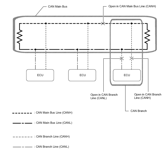
Tech Tips
-
This waveform is measured between terminals CANH and GND, and terminals CANL and GND of the central gateway ECU (network gateway ECU). (Use this as a reference for diagnosis of CAN communication lines.)
-
When malfunctions in multiple ECUs are suspected based on the CAN bus check and DTCs checked using the GTS, check the resistance of the CAN bus using an ohmmeter first. If no problems are found, check the following waveforms.
Click here
-
If a waveform is not similar to one of the following 3 patterns (Group 1), then an open in a CAN main bus line, an open in a CAN branch line, or a short between a CAN line (CANH or CANL) and ground is suspected (Group 2).
-
Wiggle the connector and wire harness to check if the waveform changes.
-
CAN bus waveforms (Group 1)
-
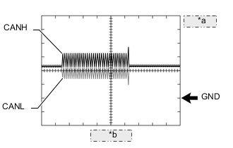
*a 1 V/DIV. *b 50 μs/DIV. Normal waveform
-
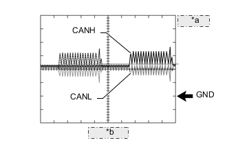
*a 1 V/DIV. *b 50 μs/DIV. Open in both of the lines (CANH and CANL) of a CAN branch
Tech Tips
-
Waveforms (waveforms shown using dotted lines) are not present from an ECU or sensor connected to a CAN branch with an open circuit in both lines. (Waveforms from other ECUs or sensors are normal.)
-
Because this waveform is similar to a normal waveform, instead of using the waveform, the malfunctioning part can be narrowed down by performing a CAN bus check.
-
-
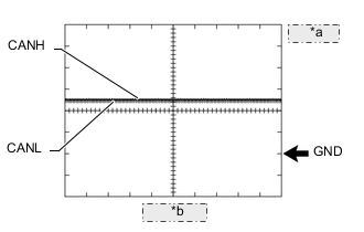
*a 1 V/DIV. *b 50 μs/DIV. Short between the CAN bus lines (CANH and CANL)
Tech Tips
-
Waveforms disappear.
-
If the malfunction is in an ECU, disconnecting the ECU will change the waveform. If the waveform does not change, a malfunction in the wire harness is suspected.
-
-
-
CAN bus waveforms (reference) (Group 2)
Note
The following CAN bus waveforms can be used only as reference. the actual measured waveform may differ significantly depending on the location of the open or short circuit.
-
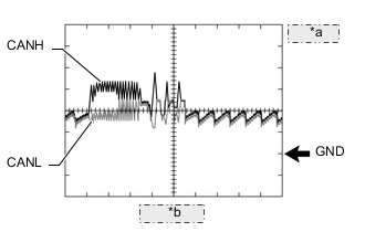
*a 1 V/DIV. *b 50 μs/DIV. Open in a CAN branch line (CANH)
Tech Tips
-
An abnormal waveform is output from an ECU with an open in one of its CAN branch lines. Because this abnormal output interferes with the signals from other ECUs, the output of other ECUs will also appear abnormal.
-
Narrow down the malfunctioning part by checking DTCs or performing a CAN bus check, or by checking waveform changes when ECUs or sensors are disconnected. the waveform will change to one for an open in both sides of a CAN branch when the ECU or sensor with an open CAN branch line is disconnected.
-
-
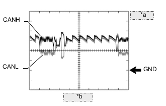
*a 1 V/DIV. *b 50 μs/DIV. Open in a CAN branch line (CANL)
Tech Tips
-
An abnormal waveform is output from an ECU with an open in one of its CAN branch lines. Because this abnormal output interferes with the signals from other ECUs, the output of other ECUs will also appear abnormal.
-
Narrow down the malfunctioning part by checking DTCs or performing a CAN bus check, or by checking waveform changes when ECUs or sensors are disconnected. the waveform will change to one for an open in both sides of a CAN branch when the ECU or sensor with an open CAN branch line is disconnected.
-
-
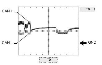
*a 1 V/DIV. *b 50 μs/DIV. Open in a CAN main bus line (CANH)
Tech Tips
-
Waveforms of ECUs or sensors that are closer to the central gateway ECU (network gateway ECU) than the open part are almost normal.
-
Waveforms of ECUs or sensors that are on the opposite side of the central gateway ECU (network gateway ECU) from the open part are abnormal.
-
An open in a CAN main bus line can be confirmed by measuring the resistance between the CANH and CANL terminals of any CAN branch.
-
-
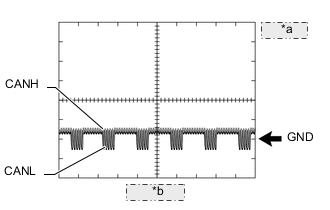
*a 1 V/DIV. *b 50 μs/DIV. Short between a CAN bus line (CANH) and ground
Tech Tips
-
Narrow down the shorted part by checking for waveform changes when disconnecting connectors from the CAN junction connectors or when disconnecting ECUs or sensors.
-
A short to ground in the CANH line can be confirmed by measuring the resistance between CANH and ground using an ohmmeter.
-
-
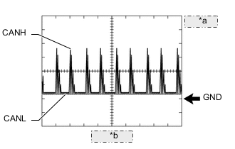
*a 1 V/DIV. *b 50 μs/DIV. Short between a CAN bus line (CANL) and ground
Tech Tips
-
Narrow down the shorted part by checking for waveform changes when disconnecting connectors from the CAN junction connectors or when disconnecting ECUs or sensors.
-
A short to ground in the CANL line can be confirmed by measuring the resistance between CANL and ground using an ohmmeter.
-
-
-
-
DATA SENDING/RECEIVING TABLE
-
Data sending/receiving table
Tech Tips
If Data List items related to sent/received data are not displayed properly, the part for which communication is interrupted can be determined using the table below.
Data Detected and Sent by Can be Checked in Data List Relevant Data List Item Relevant Data List Item Can be Checked in Data List Cannot be Checked in Data List Selected System*3 Data List Items Engine speed ECM
-
Absorber control ECU
-
Combination meter assembly
-
Rack and pinion power steering gear assembly
-
Air conditioning amplifier assembly
-
Main body ECU (multiplex network body ECU)
-
Certification ECU (smart key ECU assembly)
-
Airbag ECU assembly
-
Pedestrian detection ECU assembly
-
Stereo component equalizer assembly
-
Radio receiver assembly
-
DCM (telematics transceiver)
-
Bus buffer ECU
-
Clearance warning ECU assembly
Engine Engine Speed Adaptive Variable Suspension System Engine Speed Combination Meter Engine RPM EMPS Engine Revolution Engine coolant temperature ECM
-
Air conditioning amplifier assembly
-
Combination meter assembly
-
Rack and pinion power steering gear assembly
-
Radio receiver assembly
-
Skid control ECU assembly
Engine Ambient Temperature Air Conditioner Engine Coolant Temp Combination Meter Coolant Temperature Shift position Hybrid vehicle control ECU
-
No. 2 position control ECU assembly
-
Position control ECU assembly
-
Clearance warning ECU assembly
-
Parking assist ECU
-
Radio receiver assembly
-
Blind spot monitor sensor RH
-
Front side radar sensor RH
-
Main body ECU (multiplex network body ECU)
-
Headlight ECU sub-assembly LH
-
Combination meter assembly*1
-
Airbag ECU assembly
-
Pedestrian detection ECU assembly
-
Tire pressure warning ECU and receiver
-
Front steering control ECU
-
Rear television camera assembly
-
Driving support ECU assembly
-
Forward recognition camera
-
Bus buffer ECU
-
Absorber control ECU
-
Skid control ECU assembly
-
Luggage closer motor assembly
-
DCM (telematics transceiver)
Hybrid Control Shift Position Navigation System Reverse Signal Blind Spot Monitor Master Reverse (Only for AT/CVT) Driver Seat Shift SW Position Passenger Seat Shift SW Position Panoramic View Monitor Shift R Position Advanced Parking Guidance/ICS/Intuitive P/A Reverse Signal Front Side Radar Master Shift SW Status (R Range) Stop light switch signal Hybrid vehicle control ECU -
-
Main body ECU (multiplex network body ECU)
-
Combination meter assembly
-
Airbag ECU assembly
-
Pedestrian detection ECU assembly
-
Radio receiver assembly
-
Blind spot monitor sensor RH
Hybrid Control Stop Light Switch Wheel speed Skid control ECU assembly
-
Absorber control ECU
-
Headlight ECU sub-assembly LH
-
Hybrid vehicle control ECU
-
Parking brake ECU assembly
-
Rack and pinion power steering gear assembly
-
Suspension control ECU
-
Airbag ECU assembly
-
Pedestrian detection ECU assembly
-
Front steering control ECU
-
Blind spot monitor sensor RH
-
Driving support ECU assembly
-
Forward recognition camera
-
Stereo component equalizer assembly
-
Radio receiver assembly
-
Rear television camera assembly
-
Front side radar sensor RH
-
Clearance warning ECU assembly
-
Pedestrian detection ECU assembly
ABS/VSC/TRC
-
FR Wheel Speed
-
FL Wheel Speed
-
RR Wheel Speed
-
RL Wheel Speed
Air suspension
-
FR Wheel Speed
-
FL Wheel Speed
-
RR Wheel Speed
-
RL Wheel Speed
Adaptive Suspension System
-
FR Wheel Speed
-
FL Wheel Speed
-
RR Wheel Speed
-
RL Wheel Speed
EMPS
-
Wheel Speed Right
-
Wheel Speed Left
AFS
-
FR Wheel Speed
-
FL Wheel Speed
Electric Parking Brake
-
FR Wheel Speed
-
FL Wheel Speed
-
RR Wheel Speed
-
RL Wheel Speed
Hybrid Control
-
FR Wheel Speed
-
FL Wheel Speed
-
RR Wheel Speed
-
RL Wheel Speed
Vehicle speed Skid control ECU assembly
-
Front steering control ECU
-
Meter mirror sub-assembly
-
Combination meter assembly
-
Rear steering control ECU
-
Hybrid vehicle control ECU
-
Shift control ECU
-
Parking brake ECU assembly
-
Rack and pinion power steering gear assembly
-
Driving support ECU assembly
-
Radio receiver assembly
-
Headlight ECU sub-assembly LH
-
Main body ECU (multiplex network body ECU)
-
Certification ECU (smart key ECU assembly)
-
Airbag ECU assembly
-
Pedestrian detection ECU assembly
-
Forward recognition camera
-
Stereo component equalizer assembly
-
Sub-battery with control assembly
-
Clearance warning ECU assembly
-
Parking assist ECU
-
Seat belt control ECU
-
Rear television camera assembly
-
DCM (telematics transceiver)
ABS/VSC/TRC Vehicle Speed VGRS Vehicle Speed Navigation System Vehicle Speed Combination Meter Vehicle Speed Meter EMPS Meter Vehicle Velocity AFS Vehicle Speed Electric Parking Brake Vehicle Speed Radar Cruise2 Vehicle Speed Hybrid Control Vehicle Speed Head Up Display Vehicle Speed Meter DRS Vehicle Speed Driving support ECU assembly - Airbag ECU assembly Radar Cruise2 Vehicle Speed Combination meter assembly*2
-
Position control ECU assembly
-
No. 2 position control ECU assembly
-
Multiplex tilt and telescopic ECU
-
Air conditioning amplifier assembly
-
Main body ECU (multiplex network body ECU)
-
Certification ECU (smart key ECU assembly)
-
DCM (telematics transceiver)
-
Bus buffer ECU
-
Luggage closer motor assembly
Combination Meter Vehicle Speed Meter Driver Seat Vehicle Speed Passenger Seat Vehicle Speed Tilt&Telescopic Vehicle Speed Ambient temperature Air conditioning amplifier assembly
-
Battery ECU assembly
-
Hybrid vehicle control ECU
-
ECM
-
Inverter with converter assembly
-
Meter mirror sub-assembly
-
Combination meter assembly
-
Rack and pinion power steering gear assembly
-
Front steering control ECU
-
Parking brake ECU assembly
-
Main body ECU (multiplex network body ECU)
-
Forward recognition camera
-
Radio receiver assembly
-
DCM (telematics transceiver)
-
Clearance warning ECU assembly
-
Bus buffer ECU
-
Suspension control ECU
-
Rear power seat switch (rear multi operation panel)
Air Conditioner Ambient Temp Sensor VGRS Ambient Temperature Combination Meter
-
Ambient Temperature (Celsius)
-
Ambient Temperature (Fahrenheit)
Electric Parking Brake Ambient Temperature Hybrid Control Ambient Temperature EMPS Thermistor Temperature HV Battery Ambient Temperature Engine Ambient Temperature Head Up Display
-
Ambient Temperature (Celsius)
-
Ambient Temperature (Fahrenheit)
Motor Generator Ambient Temperature Steering angle signal Steering sensor
-
Skid control ECU assembly
-
Absorber control ECU
-
Front steering control ECU
-
Headlight ECU sub-assembly LH
-
Rack and pinion power steering gear assembly
-
Blind spot monitor sensor RH
-
Driving support ECU assembly
-
Front side radar sensor RH
-
Main body ECU (multiplex network body ECU)
-
Combination meter assembly
-
Airbag ECU assembly
-
Hybrid vehicle control ECU
-
Pedestrian detection ECU assembly
-
Rear television camera assembly
-
Forward recognition camera
-
Radio receiver assembly
-
Suspension control ECU
-
Parking assist ECU
-
Clearance warning ECU assembly
ABS/VSC/TRC
-
Steering Angle Sensor
-
Steering Angle Value
Front Side Radar Master Steering Angle Adaptive Suspension System Steering Angle VGRS
-
Steering Angle
-
Steering Angle Sensor Communication Protocol
EMPS Steering Angle AFS Steering Sens Signal Blind Spot Monitor Master Steering Angle Radar Cruise2 Steering Angle Signal Door courtesy Main body ECU (multiplex network body ECU)
-
Seat belt control ECU
-
Position control ECU assembly
-
No. 2 position control ECU assembly
-
Front multiplex network door ECU LH
-
Front multiplex network door ECU RH
-
Combination meter assembly
-
Hybrid vehicle control ECU
-
Parking brake ECU assembly
-
Forward recognition camera
-
Stereo component equalizer assembly
-
Radio receiver assembly
-
DCM (telematics transceiver)
-
Battery ECU assembly
-
Air conditioning amplifier assembly
-
Certification ECU (smart key ECU assembly)
-
Rear power seat switch
-
Suspension control ECU
-
Parking assist ECU
-
Rear multiplex network door ECU LH
-
Rear multiplex network door ECU RH
-
Bus buffer ECU
Main Body
-
FR Door Courtesy SW
-
FL Door Courtesy SW
-
RR Door Courtesy SW
-
RL Door Courtesy SW
Driver Seat D-Door Courtesy Passenger Seat P-Door Courtesy Seat Belt Control
-
Driver Side Door Courtesy Switch Status
-
Passenger Side Door Courtesy Switch Status
Luggage courtesy Main body ECU (multiplex network body ECU) -
-
Certification ECU (smart key ECU assembly)
-
Combination meter assembly
-
Suspension control ECU
-
Parking assist ECU
-
Hybrid vehicle control ECU
-
Rear television camera assembly
-
Radio receiver assembly
-
DCM (telematics transceiver)
-
Bus buffer ECU
- - Luggage closer motor assembly - Main body ECU (multiplex network body ECU) - -
-
*1: Although the received contents cannot be checked in the Data List, whether or not the data is received normally can be checked by observing the combination meter assembly.
-
*2: The combination meter assembly receives a vehicle speed signal from the skid control ECU assembly and sends the signal to other ECUs.
-
*3: According to the display on the GTS, read the Data List.
-
Enter the following menus: Powertrain / Engine / Data List
w/ Canister Pump Module: Click here
w/o Canister Pump Module: Click here
-
Enter the following menus: Powertrain / Motor Generator / Data List
-
Enter the following menus: Powertrain / HV Battery / Data List
-
Enter the following menus: Powertrain / Radar Cruise 2 / Data List
w/ Dynamic Radar Cruise Control System (for Stereo Camera Type): Click here
w/ Dynamic Radar Cruise Control System (for Mono Camera Type): Click here
-
Enter the following menus: Powertrain / Hybrid Control / Data List
-
Enter the following menus: Chassis / EMPS / Data List
-
Enter the following menus: Chassis / ABS/VSC/TRC / Data List
-
Enter the following menus: Chassis / DRS / Data List
-
Enter the following menus: Chassis / VGRS / Data List
-
Enter the following menus: Body Electrical / Head Up Display / Data List
-
Enter the following menus: Body Electrical / Combination Meter / Data List
-
Enter the following menus: Chassis / Air suspension / Data List
-
Enter the following menus: Chassis / Electric Parking Brake / Data List
-
Enter the following menus: Body Electrical / Air Conditioner / Data List
-
Enter the following menus: Body Electrical / Navigation System / Data List
-
Enter the following menus: Chassis / Panoramic View Monitor / Data List
-
Enter the following menus: Body Electrical / Driver Seat / Data List
-
Enter the following menus: Body Electrical / Passenger Seat / Data List
-
Enter the following menus: Body Electrical / Blind Spot Monitor Master / Data List
-
Enter the following menus: Body Electrical / IPA/ICS/Clearance Sonar / Data List
-
Enter the following menus: Body Electrical / AFS / Data List
-
Enter the following menus: Body Electrical / Front Side Radar Master / Data List
-
Enter the following menus: Body Electrical / Tilt&Telescopic / Data List
-
Enter the following menus: Body Electrical / Main Body / Data List
-
Enter the following menus: Chassis / Adaptive Variable Suspension System / Data List
-
Enter the following menus: Body Electrical / Seat Belt Control / Data List
-
-