POWER MIRROR CONTROL SYSTEM Power Mirror Surface Position is not Memorized or does not Return to Memorized Position
DESCRIPTION
The front multiplex network door ECU LH and front multiplex network door ECU RH memorize the mirror position when a memorization request signal is received, and move the mirror to the memorized position when a recall request signal is received.
WIRING DIAGRAM
Figure 1. for LH Side:
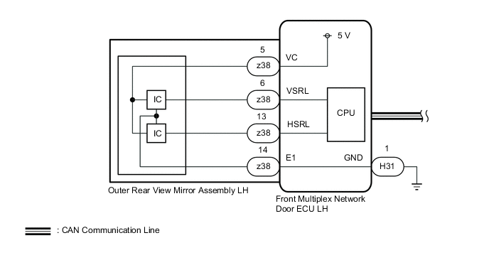
Figure 2. for RH Side:
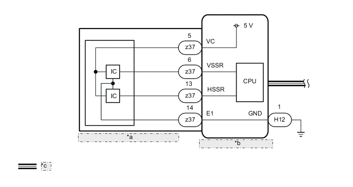
| *a | Outer Rear View Mirror Assembly RH |
| *b | Front Multiplex Network Door ECU RH |
| *c | CAN Communication Line |
CAUTION / NOTICE / HINT
Note
-
The power mirror control system uses the CAN communication system. First, confirm that there is no malfunction in the CAN communication system. Refer to the How to Proceed with Troubleshooting procedure.
-
Check that the memory and reactivation function of front power seat system is normal before performing the following procedure.
PROCEDURE
-
PROBLEM SYMPTOMS CONFIRMATION
-
Check the problem symptoms.
Result Result Proceed to LH side power mirror surface position is not memorized or does not return to memorized position A RH side power mirror surface position is not memorized or does not return to memorized position B
B 
READ VALUE USING GTS Click here
A 
-
-
READ VALUE USING GTS
-
Connect the GTS to the DLC3.
-
Turn the power switch on (IG).
-
Turn the GTS on.
-
Enter the following menus: Body Electrical / Front Left Door / Data List.
-
Read the Data List according to the display on the GTS.
Body Electrical > Front Left Door > Data ListTester Display Measurement Item Range Normal Condition Diagnostic Note Mirror Vertical Sensor Vol Vertical mirror position MIN: 0, MAX: 5 V 0 to 5 V - Mirror Horizontal Sensor Vol Horizontal mirror position MIN: 0, MAX: 5 V 0 to 5 V -
Body Electrical > Front Left Door > Data ListTester Display Mirror Vertical Sensor Vol Mirror Horizontal Sensor Vol OK The sensor voltage changes depending on the mirror surface position. Result Proceed to OK NG
OK 
REPLACE FRONT MULTIPLEX NETWORK DOOR ECU LH Click here
NG
-
-
INSPECT OUTER REAR VIEW MIRROR ASSEMBLY LH
-
Remove the outer rear view mirror assembly LH.
-
Connect 3 dry cell batteries (1.5 V) in series.
Note
Do not use rechargeable batteries as they may not output a voltage of 1.5 V.
-
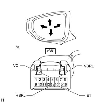
*a Component without connector connected
(Outer Rear View Mirror Assembly LH)
Connect the positive (+) end of a series of batteries to terminal 5 (VC) and the negative (-) end to terminal 14 (E1), and check that the voltage between the terminals change as shown in the table below depending on the position of the mirror surface.
Note
Do not apply a voltage of 6 V or higher between the terminals.
-
Measure the voltage according to the value(s) in the table below.
Standard Voltage Tester Connection Mirror Surface Position Specified Condition z38-6 (VSRL) - z38-14 (E1) Down ←→ Up 0 to 4.5 V z38-13 (HSRL) - z38-14 (E1) Out ←→ In 0 to 4.5 V OK The voltage changes depending on the mirror surface position. Result Proceed to OK NG
OK
REPLACE FRONT MULTIPLEX NETWORK DOOR ECU LH Click here
NG
REPLACE OUTER REAR VIEW MIRROR ASSEMBLY LH Click here
-
-
READ VALUE USING GTS
-
Connect the GTS to the DLC3.
-
Turn the power switch on (IG).
-
Turn the GTS on.
-
Enter the following menus: Body Electrical / Front Right Door / Data List.
-
Read the Data List according to the display on the GTS.
Body Electrical > Front Right Door > Data ListTester Display Measurement Item Range Normal Condition Diagnostic Note Mirror Vertical Sensor Vol Vertical mirror position MIN: 0, MAX: 5 V 0 to 5 V - Mirror Horizontal Sensor Vol Horizontal mirror position MIN: 0, MAX: 5 V 0 to 5 V -
Body Electrical > Front Right Door > Data ListTester Display Mirror Vertical Sensor Vol Mirror Horizontal Sensor Vol OK The sensor voltage changes depending on the mirror surface position. Result Proceed to OK NG
OK
REPLACE FRONT MULTIPLEX NETWORK DOOR ECU RH Click here
NG
-
-
INSPECT OUTER REAR VIEW MIRROR ASSEMBLY RH
-
Remove the outer rear view mirror assembly RH.
-
Connect 3 dry cell batteries (1.5 V) in series.
Note
Do not use rechargeable batteries as they may not output a voltage of 1.5 V.
-
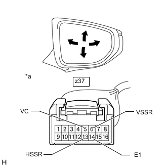
*a Component without connector connected
(Outer Rear View Mirror Assembly RH)
Connect the positive (+) end of a series of batteries to terminal 5 (VC) and the negative (-) end to terminal 14 (E1), and check that the voltage between the terminals change as shown in the table below depending on the position of the mirror surface.
Note
Do not apply a voltage of 6 V or higher between the terminals.
-
Measure the voltage according to the value(s) in the table below.
Standard Voltage Tester Connection Mirror Surface Position Specified Condition z37-6 (VSSR) - z37-14 (E1) Down ←→ Up 0 to 4.5 V z37-13 (HSSR) - z37-14 (E1) Out ←→ In 0 to 4.5 V OK The voltage changes depending on the mirror surface position. Result Proceed to OK NG
OK
REPLACE FRONT MULTIPLEX NETWORK DOOR ECU RH Click here
NG
REPLACE OUTER REAR VIEW MIRROR ASSEMBLY RH Click here
-