WIPER AND WASHER SYSTEM Washer Motor Circuit
DESCRIPTION
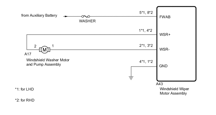
When the windshield washer motor and pump assembly receives signals from the windshield wiper switch assembly (washer switch) it operates to spray washer fluid from the washer nozzle sub-assemblies.
WIRING DIAGRAM
CAUTION / NOTICE / HINT
Note
Inspect fuses for circuits related to this system before performing the following inspection procedure.
PROCEDURE
-
PERFORM ACTIVE TEST USING GTS
-
Perform the Active Test according to the display on the GTS.
Body Electrical > Wiper > Active TestTester Display Measurement Item Control Range Diagnostic Note Front Washer Operates the open side washer OFF or ON - Rear Washer Operates the closed side washer OFF or ON -
Body Electrical > Wiper > Active TestTester Display Front Washer
Body Electrical > Wiper > Active TestTester Display Rear Washer OK Washer fluid sprays from each washer nozzle. Result Proceed to OK NG
OK 
PROCEED TO NEXT SUSPECTED AREA SHOWN IN PROBLEM SYMPTOMS TABLE Click here
NG 
-
-
CHECK WINDSHIELD WASHER MOTOR AND PUMP ASSEMBLY
-
Disconnect the A17 windshield washer motor and pump assembly connector.
-
Inspect the windshield washer motor and pump assembly.
Result Proceed to OK NG
NG
REPLACE WINDSHIELD WASHER MOTOR AND PUMP ASSEMBLY Click here
OK
-
-
CHECK HARNESS AND CONNECTOR (WINDSHIELD WASHER MOTOR AND PUMP ASSEMBLY - WINDSHIELD WIPER MOTOR ASSEMBLY)
-
Disconnect the A17 windshield washer motor and pump assembly connector.
-
Disconnect the A43 windshield wiper motor assembly connector.
-
Measure the resistance according to the value(s) in the table below.
Standard Resistance for LHD Tester Connection Condition Specified Condition A17-2 - A43-1 (WSR+) Always Below 1 Ω A17-1 - A43-2 (WSR-) Always Below 1 Ω A17-2 or A43-1 (WSR+) - Body ground Always 10 kΩ or higher A17-1 or A43-2 (WSR-) - Body ground Always 10 kΩ or higher for RHD Tester Connection Condition Specified Condition A17-2 - A43-4 (WSR+) Always Below 1 Ω A17-1 - A43-3 (WSR-) Always Below 1 Ω A17-2 or A43-4 (WSR+) - Body ground Always 10 kΩ or higher A17-1 or A43-3 (WSR-) - Body ground Always 10 kΩ or higher Result Proceed to OK NG
NG
REPAIR OR REPLACE HARNESS OR CONNECTOR
OK
-
-
CHECK HARNESS AND CONNECTOR (WINDSHIELD WIPER MOTOR ASSEMBLY - BATTERY AND BODY GROUND)
-
Disconnect the A43 windshield wiper motor assembly connector.
-
Measure the resistance according to the value(s) in the table below.
Standard Resistance for LHD Tester Connection Condition Specified Condition A43-4 (GND) - Body ground Always Below 1 Ω for RHD Tester Connection Condition Specified Condition A43-1 (GND) - Body ground Always Below 1 Ω -
Measure the voltage according to the value(s) in the table below.
Standard Voltage for LHD Tester Connection Switch Condition Specified Condition A43-5 (FWAB) - Body ground Power switch off 11 to 14 V for RHD Tester Connection Switch Condition Specified Condition A43-8 (FWAB) - Body ground Power switch off 11 to 14 V Result Proceed to OK NG
OK
REPLACE WINDSHIELD WIPER MOTOR ASSEMBLY Click here
NG
REPAIR OR REPLACE HARNESS OR CONNECTOR
-