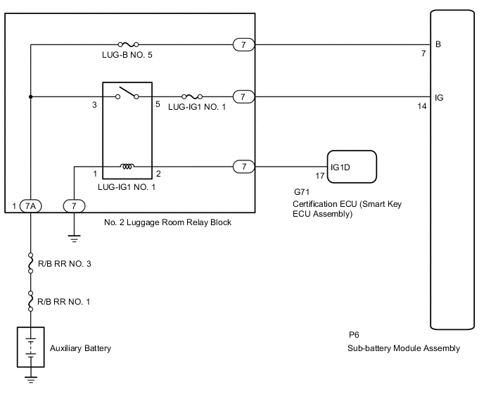
SUB BATTERY SYSTEM ECU Power Source Circuit
DESCRIPTION
Power is supplied to the B terminal of the sub-battery module assembly from the auxiliary battery power source.
The B terminal supplies power to the sub-battery ECU, which uses it for sub-battery charging and discharging control, condition judgment, DTC output and freeze frame data output.
When the LUG-IG1 NO. 1 relay is turned on while the power switch is on (IG), power is supplied to the IG terminal of the sub-battery module.
WIRING DIAGRAM
CAUTION / NOTICE / HINT
Note
Inspect the fuses for circuits related to this system before performing the following procedure.
PROCEDURE
-
INSPECT SUB-BATTERY MODULE ASSEMBLY (B TERMINAL VOLTAGE)
-
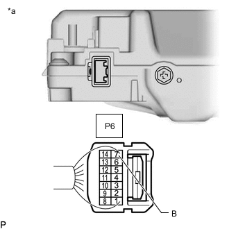
*a Front view of wire harness connector
(to Sub-battery Module Assembly)
Measure the voltage according to the value(s) in the table below.
Standard Voltage Tester Connection Condition Specified Condition P6-7 (B) - Body ground Power switch off 11 to 14 V Result Proceed to OK NG
NG 
REPAIR OR REPLACE HARNESS OR CONNECTOR (AUXILIARY BATTERY - SUB-BATTERY MODULE ASSEMBLY)
OK 
-
-
INSPECT SUB-BATTERY MODULE ASSEMBLY (IG TERMINAL VOLTAGE)
-
Disconnect the sub-battery module assembly connector.
-
Turn the power switch on (IG).
-
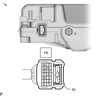
*a Rear view of wire harness connector
(to Sub-battery Module Assembly)
Measure the voltage according to the value(s) in the table below.
Standard Voltage Tester Connection Condition Specified Condition P6-14 (IG) - Body ground Power switch on (IG) 11 to 14 V -
Reconnect the sub-battery module assembly connector.
Result Proceed to OK NG
OK
CHECK FOR INTERMITTENT PROBLEMS Click here
NG
-
-
CHECK HARNESS AND CONNECTOR (LUG-IG NO. 1 RELAY - SUB-BATTERY MODULE ASSEMBLY)
-
Remove the LUG-IG NO. 1 relay from the No. 2 luggage room relay block.
-
Disconnect the sub-battery module assembly connector.
-
Measure the resistance according to the value(s) in the table below.
Standard Resistance Tester Connection Condition Specified Condition LUG-IG NO. 1 relay terminal 5 - P6-14 (IG) Always Below 1 Ω LUG-IG NO. 1 relay terminal 5 or P6-14 (IG) - Body ground and other terminals Always 10 kΩ or higher Result Proceed to OK NG
OK
GO TO ENTRY AND START SYSTEM (FOR START FUNCTION) Click here
NG
REPAIR OR REPLACE HARNESS OR CONNECTOR
-