CAUTION / NOTICE / HINT
-
Before replacing the main body ECU (multiplex network body ECU), refer to Service Bulletin.
-
When installing the main body ECU (multiplex network body ECU), always replace it with a new one.
-
Use the same procedure for RHD and LHD vehicles.
-
The procedure listed below is for LHD vehicles.
PROCEDURE
- Click here
INSTALL MAIN BODY ECU (MULTIPLEX NETWORK BODY ECU)
-
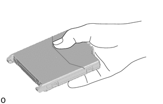
Hold the main body ECU (multiplex network body ECU) with your dominant hand.
Note: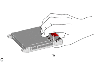
*a Connector
-
Do not touch the connector.
-
Make sure foreign matter does not enter the terminals.
-
-
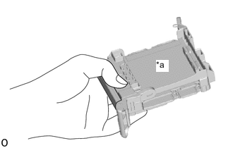
*a Fitting Surface Hold the instrument panel junction block assembly with your other hand.
Note:Make sure there is no foreign matter in the fitting surface.
-

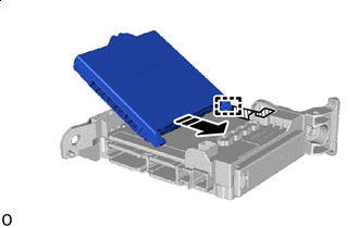
*a 20° or more 
Install in this Direction 
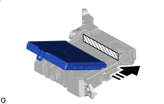
Housing Sidewall Set the guide of the main body ECU (multiplex network body ECU) against the housing sidewall.
Tip:Make sure the angle between the instrument panel junction block assembly and the main body ECU (multiplex network body ECU) is 20° or more.
-
Install in this Direction Housing Sidewall Slide the guide of the main body ECU (multiplex network body ECU) along the housing sidewall in the direction indicated by the arrow.
-
Install in this Direction Side A Slide it until it contacts side A.
-
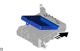
Install in this Direction Contact side A.
Note:Do not contact side A with the main body ECU (multiplex network body ECU) too hard.
-
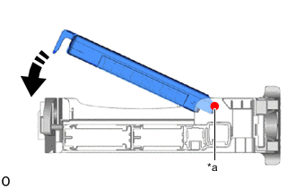
*a Center of Rotation(Contacts Surface A) Rotate in this Direction 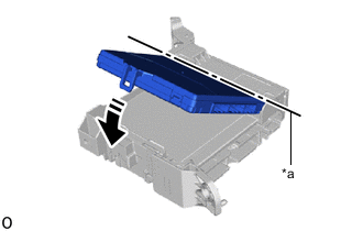
*a Center of Rotation(Contacts Surface A) Rotate in this Direction While pressing the main body ECU (multiplex network body ECU) against side A (center of rotation) of the instrument panel junction block assembly, rotate it until it enters the lock of the instrument panel junction block assembly.
Tip:The center of rotation is the one that contacts surface A.
-
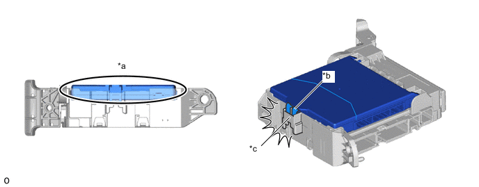
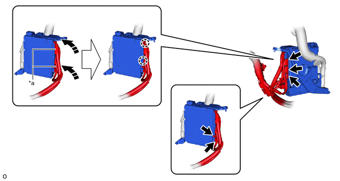
*a Before Locking *b Main Body ECU (Multiplex Network Body ECU) Lock *c Instrument Panel Junction Block Assembly Lock - - Rotate it until it enters the lock of the instrument panel junction block assembly.
-
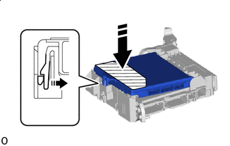
Install in this Direction Pressing Area Press the pressing area of the main body ECU (multiplex network body ECU).
Note:
-
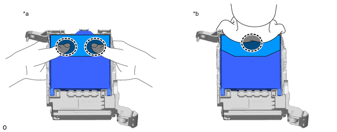
*a Press the 2 sides of the main body ECU (multiplex network body ECU) with both hands. *b Press the center of the main body ECU (multiplex network body ECU) with one hand. 
Place fingers or the palm of your hand here - - Press it in one of the following ways.
-
Check the engagement of the main body ECU (multiplex network body ECU) and the instrument panel junction block assembly by the locking sound.
-
Do not hit on or put your weight on the main body ECU (multiplex network body ECU) when engaging the main body ECU (multiplex network body ECU).
-
-
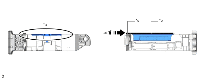
*a After Locking (Height Matches) *b Back Side of Main Body ECU (Multiplex Network Body ECU) *c Rib Surrounding Instrument Panel Junction Block Assembly - - Confirm Visually - - 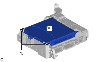
*a Back Side of Main Body ECU (Multiplex Network Body ECU) *b Rib Surrounding Instrument Panel Junction Block Assembly Check that the back side of the main body ECU (multiplex network body ECU) and the rib surrounding the instrument panel junction block assembly are the same height.
-
Attach the claw.
-
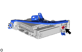
Install the wiring harness clamp bracket with the nut.
8.0 N*m 82 kgf*cm 71 in.*lbf Note: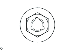
If the removed nut is the same shape as that shown in the illustration, replace it the supplied replacement part.
-
- Click here
INSTALL INSTRUMENT PANEL JUNCTION BLOCK ASSEMBLY WITH MAIN BODY ECU
-
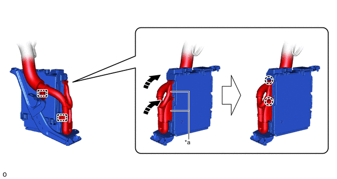
*a Lever Connector - - Rotate in this Direction - - Attach the claw to connect the 2 lever connectors.
Note:Be sure to connect the lever connector securely.
-
Attach the clamp.
-
*a Lever Connector - - Rotate in this Direction - - Connect the 5 connectors.
-
Attach the claw to connect the 2 lever connectors.
Note:Be sure to connect the lever connector securely.
-
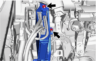
Install the instrument panel junction block assembly with main body ECU with the 2 nuts.
Note:
If the removed nut is the same shape as that shown in the illustration, replace it the supplied replacement part.
8.0 N*m 82 kgf*cm 71 in.*lbf -
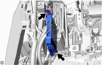
Connect the ECU with the 2 nuts.
Note:
If the removed nut is the same shape as that shown in the illustration, replace it the supplied replacement part.
-
- Click here
INSTALL NO. 3 INSTRUMENT PANEL TO COWL BRACE SUB-ASSEMBLY
- Click here
INSTALL NO. 1 HEATER TO REGISTER DUCT
- Click here
INSTALL NO. 1 AIR DUCT SUB-ASSEMBLY
- Click here
INSTALL LOWER NO. 1 INSTRUMENT PANEL AIRBAG ASSEMBLY