SUB BATTERY SYSTEM TERMINALS OF ECM
-
Figure 1. Sub-battery Module Assembly
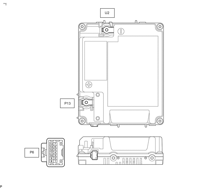
*1 Sub-battery Module Assembly - - Terminal No.
(Symbol)
Wiring Color Input/Output Terminal Description Condition Specified Condition P13-1 (+BAT) - U2-1 (-BAT) B-W - B-Y IN/OUT Sub-battery voltage 5 seconds elapse after turning power switch on (IG) 11 to 14 V P6-1 (RO) - U2-1 (-BAT) B - B-Y OUT Sub-battery condition signal Power switch on (IG) Pulse generation
(See waveform 1)
P6-3 (CANH) - U2-1 (-BAT) LG - B-Y IN/OUT CAN communication line Power switch on (IG) Pulse generation
(See waveform 2)
P6-5 (BR) - U2-1 (-BAT) LG - B-Y IN Back-up request signal Power switch on (IG) Pulse generation
(See waveform 3)
P6-7 (B) - U2-1 (-BAT) R - B-Y IN Sub-battery ECU power supply Power switch off 11 to 14 V P6-8 (BUR) - U2-1 (-BAT) V - B-Y OUT Backup relay control signal Power switch on (IG) Pulse generation
(See waveform 4)
P6-10 (CANL) - U2-1 (-BAT) W - B-Y IN/OUT CAN communication line Power switch on (IG) Pulse generation
(See waveform 2)
P6-11 (RD2) - U2-1 (-BAT) SB - B-Y IN Backup relay signal Power switch on (IG) Pulse generation
(See waveform 5)
P6-12 (RD1) - U2-1 (-BAT) L - B-Y IN Backup relay signal Power switch on (IG) Pulse generation
(See waveform 6)
P6-14 (IG) - U2-1 (-BAT) P - B-Y IN IG power supply Power switch on (IG) 11 to 14 V -
Figure 2. Backup Relay
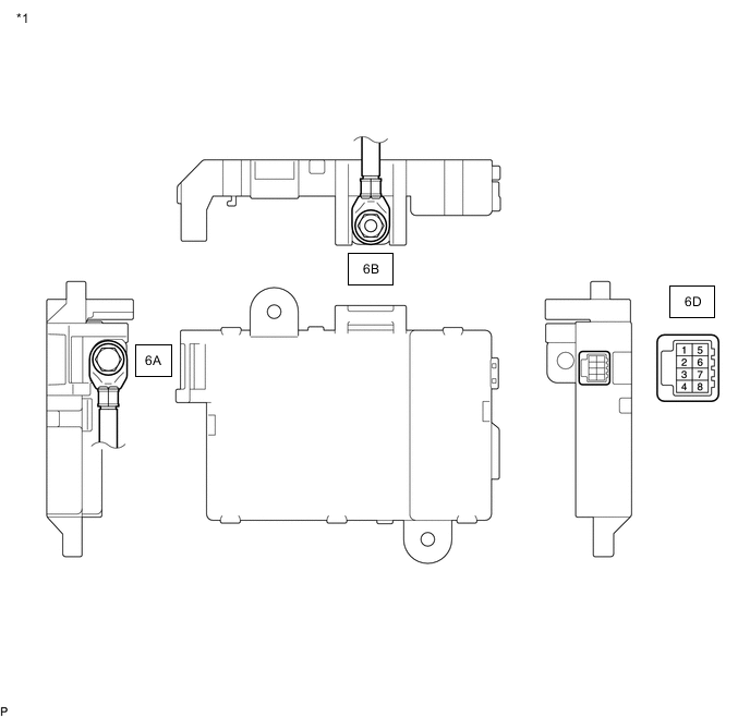
*1 Backup Relay - - Terminal No.
(Symbol)
Wiring Color Input/Output Terminal Description Condition Specified Condition 6B-1 (B) - 6D-8 (GND) B-W - W-B IN Auxiliary battery voltage Power switch off 11 to 14 V 6A-1 (BAT2) - 6D-8 (GND) B-W - W-B IN Sub-battery voltage 5 seconds elapse after turning power switch on (IG) 11 to 14 V 6D-1 (RLY1) - 6D-8 (GND) V - W-B IN Backup relay control signal Power switch on (IG) Pulse generation
(See waveform 4)
6D-6 (RD12) - 6D-8 (GND) SB - W-B OUT Backup relay condition signal Power switch on (IG) Pulse generation
(See waveform 5)
6D-3 (RD11) - 6D-8 (GND) L - W-B OUT Backup relay condition signal Power switch on (IG) Pulse generation
(See waveform 6)
-
Oscilloscope waveforms
Tech Tips
Oscilloscope waveform samples are provided here for informational purposes. Noise and fluttering waveforms have been omitted.
-
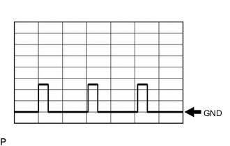
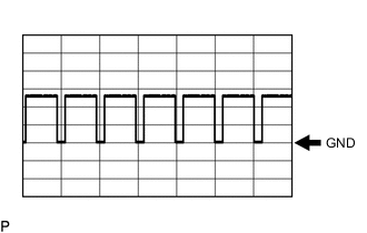
Waveform 1
Item Content Terminal P6-1 (RO) - U2-1 (-BAT) Equipment Setting 5 V/DIV, 10 ms/DIV Condition Power switch on (IG) Tech Tips
The duty ratio changes according to the vehicle condition.
-
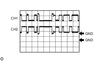
Waveform 2
Item Content Terminal CH1: P6-3 (CANH) - U2-1 (-BAT)
CH2: P6-10 (CANL) - U2-1 (-BAT)
Equipment Setting 1 V/DIV, 10 μs/DIV Condition Power switch on (IG) -
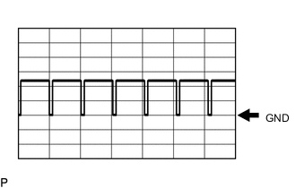
Waveform 3
Item Content Terminal P6-5 (BR) - U2-1 (-BAT) Equipment Setting 5 V/DIV, 10 ms/DIV Condition Power switch on (IG) Tech Tips
The duty ratio changes according to the vehicle condition.
-
Waveform 4
Item Content Terminal
-
P6-8 (BUR) - U2-1 (-BAT)
-
6D-1 (RLY1) - 6D-8 (GND)
Equipment Setting 5 V/DIV, 20 ms/DIV Condition Power switch on (IG) Tech Tips
The duty ratio changes according to the vehicle condition.
-
-
Waveform 5
Item Content Terminal
-
P6-11 (RD2) - U2-1 (-BAT)
-
6D-6 (RD12) - 6D-8 (GND)
Equipment Setting 5 V/DIV, 20 ms/DIV Condition Power switch on (IG) Tech Tips
The duty ratio changes according to the vehicle condition.
-
-
Waveform 6
Item Content Terminal
-
P6-12 (RD1) - U2-1 (-BAT)
-
6D-3 (RD11) - 6D-8 (GND)
Equipment Setting 5 V/DIV, 20 ms/DIV Condition Power switch on (IG) Tech Tips
The duty ratio changes according to the vehicle condition.
-
-