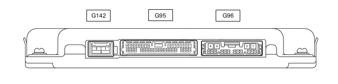
PANORAMIC VIEW MONITOR SYSTEM TERMINALS OF ECU
-
PARKING ASSIST ECU
-
Disconnect the G96 parking assist ECU connector.
-
Measure the voltage and resistance according to the value(s) in the table below.
Terminal No. (Symbol) Wiring Color Terminal Description Condition Specified Condition G96-1 (+B) - G96-4 (GND1) LA-G - LA Power source signal Power switch off 11 to 14 V G96-4 (GND1) - Body ground LA - Body ground Ground Always Below 1 Ω G96-3 (IG) - G96-4 (GND1) LA-V - LA IG power source signal Power switch on (IG) 11 to 14 V Power switch off Below 1 V G96-2 (ACC) - G96-4 (GND1) LA-R - LA ACC power source signal Power switch on (ACC) 11 to 14 V Power switch off Below 1 V -
Reconnect the G96 and G95 parking assist ECU connector.
-
Measure the voltage, resistance and waveform according to the value(s) in the table below.
Terminal No. (Symbol) Wiring Color Terminal Description Condition Specified Condition G95-6 (RSW+) - G96-4 (GND1) L - LA Terminal required by law Panoramic image being displayed 0 to 2 V Panoramic image not being displayed 5.5 to 7.05 V G96-15 (BLSW) - Body ground P - Body ground Panoramic view monitor main switch(Integration control & panel assembly) switch signal Power switch on (IG), Panoramic view monitor main switch(Integration control & panel assembly) off 5.5 to 6.5 V Power switch on (IG), Panoramic view monitor main switch(Integration control & panel assembly) on Below 1 V G95-29 (CV+) - G95-32 (CGND) W - R Rear television camera assembly display signal input Power switch on (IG), Panoramic view monitor main switch(Integration control & panel assembly) on, camera lens not covered, displaying image Pulse generation (See waveform 1) Power switch on (IG), Panoramic view monitor main switch(Integration control & panel assembly) on, camera lens covered, blacking out screen Pulse generation (See waveform 2) G95-30 (CV-) - G96-4 (GND1) B - LA Rear television camera assembly ground Always Below 1 Ω G95-32 (CGND) - G96-4 (GND1) R - LA Rear television camera assembly ground Always Below 1 Ω G95-10 (LCV+) - G95-35 (LGND) G - W Side television camera assembly LH display signal input Power switch on (IG), Panoramic view monitor main switch(Integration control & panel assembly) on, camera lens not covered, displaying image Pulse generation (See waveform 1) Power switch on (IG), Panoramic view monitor main switch(Integration control & panel assembly) on, camera lens covered, blacking out screen Pulse generation (See waveform 2) G95-12 (LCB+) - G95-35 (LGND) B - W Power source to side television camera assembly LH Power switch on (IG) 5.5 to 7.05 V G95-34 (LCV-) - G96-4 (GND1) R - LA Side television camera assembly LH ground Always Below 1 Ω G95-35 (LGND) - G96-4 (GND1) W - LA Side television camera assembly LH ground Always Below 1 Ω G95-36 (BCV+) - G95-37 (BGND) G - W Front television camera assembly display signal input Waveform 1: Power switch on (IG), Panoramic view monitor main switch(Integration control & panel assembly) on, camera lens not covered, displaying image Pulse generation (See waveform 1) Waveform 2: Power switch on (IG), Panoramic view monitor main switch(Integration control & panel assembly) on, camera lens covered, blacking out screen Pulse generation (See waveform 2) G95-15 (BCB+) - G95-37 (BGND) B - W Power source to front television camera Power switch on (IG) 5.5 to 7.05 V G95-13 (BCV-) - G96-4 (GND1) R - LA Front television camera assembly ground Always Below 1 Ω G95-37 (BGND) - G96-4 (GND1) W - LA Front television camera assembly ground Always Below 1 Ω G95-38 (RCV+) - G95-17 (RGND) G - W Side television camera assembly RH display signal input Waveform 1: Power switch on (IG), Panoramic view monitor main switch(Integration control & panel assembly) on, camera lens not covered, displaying image Pulse generation (See waveform 1) Waveform 2: Power switch on (IG), Panoramic view monitor main switch(Integration control & panel assembly) on, camera lens covered, blacking out screen Pulse generation (See waveform 2) G95-40 (RCB+) - G95-17 (RGND) B - W Power source to side television camera assembly RH Power switch on (IG) 5.5 to 7.05 V G95-16 (RCV-) - G96-4 (GND1) R - LA Side television camera assembly RH ground Always Below 1 Ω G95-17 (RGND) - G96-4 (GND1) W - LA Side television camera assembly RH ground Always Below 1 Ω G96-9 (CA2H) - - - G96-10 (CA2L) - - - G96-11 (CANH) - - - G96-12 (CANL) - - - -
Using an oscilloscope, check the waveform.
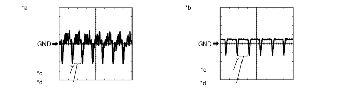
*a Waveform 1 *b Waveform 2 *c Synchronization Signal *d Video Waveform
-
Waveform 1
Measurement Condition Item Content Terminal No. (Symbol)
-
G95-29 (CV+) - G95-32 (CGND)
-
G95-10 (LCV+) - G95-35 (LGND)
-
G95-36 (BCV+) - G95-37 (BGND)
-
G95-38 (RCV+) - G95-39 (RGND)
Tool Setting 200 mV/DIV., 50 μsec./DIV. Condition
-
Waveform 1: Power switch on (IG), Panoramic view monitor main switch(Integration control & panel assembly) on, camera lens not covered, displaying image
-
Waveform 2: Power switch on (IG), Panoramic view monitor main switch(Integration control & panel assembly) on, camera lens covered, blacking out screen
Tech Tips
-
The video waveform changes according to the image sent by the television camera assembly.
-
The video waveform is constantly output when the power switch is on (ACC).
-
-
-
-
REAR TELEVISION CAMERA ASSEMBLY

-
Disconnect the L85 rear television camera assembly connector.
-
Measure the voltage on the wire harness side connector according to the value(s) in the table below.
Terminal No. (Symbol) Wiring Color Terminal Description Condition Specified Condition L85-6 (CB+) - Body ground GR - Body ground Power source Power switch on (ACC) 11 to 14 V If the result is not as specified, there may be a malfunction on the wire harness side.
-
Reconnect the L85 rear television camera assembly connector.
-
Measure the voltage and waveform according to the value(s) in the table below.
Terminal No. (Symbol) Wiring Color Terminal Description Condition Specified Condition L85-3 (CV+) - L85-2 (CV-) B - G Video signal Power switch on (IG) with the camera lens of the side television camera assembly RH not covered, displaying the panoramic image Pulse generation
(Refer to waveform 1)
Power switch on (IG) with the camera lens of the rear television camera assembly covered, blacking out the panoramic image Pulse generation
(Refer to waveform 2)
L85-5 (CGND) - Body ground BR - Body ground Shield ground Always Below 1 V Tech Tips
A waterproof connector is used for the rear television camera assembly. Therefore, inspect the waveform at the radio and display receiver assembly with the connector connected.
If the result is not as specified, the rear television camera assembly may be malfunctioning.
-
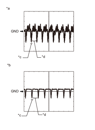
*a Waveform 1 (camera lens is not covered, displaying an image) *b Waveform 2 (camera lens is covered, blacking out the screen) *c Synchronization Signal *d Video Waveform Reference (Oscilloscope waveform):
Tech Tips
A waterproof connector is used for the rear television camera assembly. Therefore, inspect the waveform at the radio and display receiver assembly with the connector connected.
-
Waveform 1 (camera lens is not covered, displaying an image)
Item Content Measurement terminal L85-3 (CV+) - L85-2 (CV-) Measurement setting 200 mV/DIV., 50 μs./DIV. Condition Panoramic view monitor system operating Tech Tips
-
The video waveform changes according to the image sent by the rear television camera assembly.
-
The video waveform is constantly output when the power switch is on (ACC).
-
-
Waveform 2 (camera lens is covered, blacking out the screen)
Item Content Measurement terminal L85-3 (CV+) - L85-2 (CV-) Measurement setting 200 mV/DIV., 50 μs./DIV. Condition Panoramic view monitor system operating Tech Tips
-
The video waveform changes according to the image sent by the rear television camera assembly.
-
The video waveform is constantly output when the power switch is on (ACC).
-
-
-
-
RADIO RECEIVER ASSEMBLY (w/ Audio and Visual System )
-
RADIO RECEIVER ASSEMBLY (w/ Navigation System)