Click here
PROCEDURE
- Click here
INSTALL CLEARANCE WARNING ECU ASSEMBLY
-
Attach the guide to temporarily install the clearance warning ECU assembly.
-
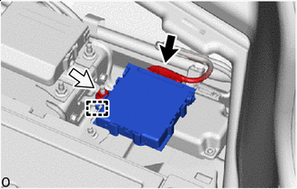

Connector 
Nut Install the clearance warning ECU assembly with the nut.
7.5 N*m 76 kgf*cm 66 in.*lbf Note: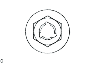
If the removed nut is the same shape as that shown in the illustration, replace it the supplied replacement part.
-
Connect the connector.
-
- Click here
INSTALL SIDE TRIM BOX
-
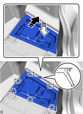

Install in this Direction (1) 
Install in this Direction (2) Attach the claw and guide to install the side trim box the direction of the arrow shown in the illustration.
-
- Click here
INSTALL LUGGAGE COMPARTMENT TRIM COVER RH
-
Install the luggage compartment trim cover RH.
-
- Click here
INITIALIZE POWER TRUNK LID CONTROL SYSTEM
- Click here
PERFORM CALIBRATION
-
w/ Parking Support Brake System:
-
w/o Parking Support Brake System:
-