Click here
-
GENERAL
-
The parking support alert system has a stationary objects function, vehicles approaching from rear function, and pedestrians behind vehicle.
-
Parking Support Alert (stationary objects) function
-
This function uses ultrasonic sensors to detect any obstacles at the corners and the rear of the vehicle. The function then informs the driver of the distance between the sensors and an obstacle as well as their positions by indicating them on the multi-information display (on the combination meter assembly), multi-display (on the multi-display) and by sounding a buzzer.
-
-
Parking Support Alert (vehicles approaching from rear) function
-
This function is a function that informs the driver of an approaching vehicle from diagonally behind. The function uses quasi-millimeter wave radar to detect the positions of and relative speed to a vehicle. When the function determines that a vehicle is approaching this vehicle, this function informs the driver of it using the indicators and buzzer.
-
-
Parking Support Alert (pedestrians behind vehicle) function
-
This function is if the rear television camera assembly detects a pedestrian when the shift lever is in R, the rear camera detection function displays a pedestrian detection icon on the multi-display and sounds the rear camera detection buzzer (blind spot monitor buzzer) to warn the driver.
-
-
-
-
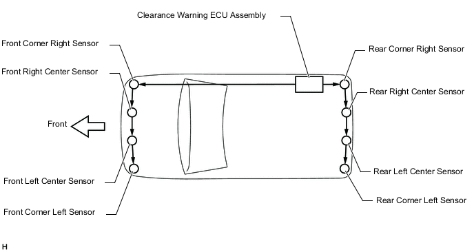
FUNCTION OF COMPONENTS
Component Function
-
Front Corner Ultrasonic Sensor (FL sensor)
-
Front Corner Ultrasonic Sensor (FR sensor)
-
Front Center Ultrasonic Sensor (FLC sensor)
-
Front Center Ultrasonic Sensor (FRC sensor)
-
Rear Corner Ultrasonic Sensor (RL sensor)
-
Rear Corner Ultrasonic Sensor (RR sensor)
-
Rear Center Ultrasonic Sensor (RLC sensor)
-
Rear Center Ultrasonic Sensor (RRC sensor)
Detects the distance between the vehicle and an obstacle
-
No. 1 Clearance Warning Buzzer
-
No. 2 Clearance Warning Buzzer
Sounds to inform the driver according to the distance to an obstacle Combination Meter Assembly
-Multi-information Display
-Clearance Sonar Off Indicator
-RCTA Off Indicator
-RCD Off Indicator
-
Transmits the ON/OFF signal to the clearance warning ECU assembly
-
Displays the location of an obstacle and the approximate distance between the vehicle and the obstacle
-
Displays a malfunction of the ultrasonic sensor to inform the driver
-
Illuminates to inform the driver while the parking support alert system power is off (the power switch is on (IG) and the parking support alert system system is off)
-
Sends the temporary mute setting signal to the clearance warning ECU assembly via CAN communication
Steering Pad Switch Assembly Enables, disables or cuts off the operation of the parking support alert system by transmitting the switch operation signal to the combination meter assembly Clearance Warning ECU Assembly
-
Judges the approximate distance between the vehicle and an obstacle based on the signals from the ultrasonic sensors and sends it to the multi-information display and radio receiver assembly
-
Judges the approximate distance between the vehicle and an obstacle based on the signals from the ultrasonic sensors, and sends it to the multi-information display, radio receiver assembly, parking assist ECU*1 or rear television camera assembly*2
-
Judges the approximate distance between the vehicle and an obstacle based on the signals from the ultrasonic sensors and sounds the buzzer
-
Receives the temporary mute setting signal and clearance sonar setting screen information from the radio receiver assembly via CAN communication
-
Receives the ultrasonic sensor information via CAN communication and sends it to the headup display
Main Body ECU (Multiplex Network Body ECU) Transmits the destination information to the clearance warning ECU assembly, rear television camera assembly*2, or blind spot monitor sensor*3 Hybrid Vehicle Control ECU Assembly Transmits the shift position signal to the clearance warning ECU assembly, rear television camera assembly*2, or blind spot monitor sensor*3 Radio Receiver Assembly
-
Sends the temporary mute setting signal and clearance sonar setting screen information to the clearance warning ECU assembly via CAN communication
Multi-display
-
Receives the video signals from the radio receiver assembly, and displays them on the display panel
-
Receives the video signals from the parking assist ECU*1 or rear television camera assembly*2, and displays them on the display panel
Parking Assist ECU*1 Receives the ultrasonic sensor information via CAN communication and sends it to the multi-display through the video signal cable Rear Television Camera Assembly*2
-
Receives the ultrasonic sensor information via CAN communication and sends it to the multi-display through the video signal cable
-
Sends a camera detection buzzer request signal to the blind spot monitor sensor via CAN communication.*3
Blind Spot Monitor Sensor*3
-
Consists of a 24 GHz radar module and an integrated processing module.
-
Illuminates or blinks the outer rear view mirror indicator on the outer mirror actuator assembly
-
Sounds the RCTA buzzer (blind spot monitor buzzer) when the RCTA function is operating.
-
Dims the outer rear view mirror indicator on the outer rear view mirror assembly.
-
Displays the RCTA icon on the multi-display when the RCTA function is operating.
-
Sends blind spot monitor system status signals to the clearance warning ECU assembly via CAN communication
RCTA Buzzer (Blind Spot Monitor Buzzer) Sounds based on a signal from the blind spot monitor sensor. Headup Display (Meter Mirror Sub-assembly)*4 Receives the ultrasonic sensor information via CAN communication and sends it to the headup display
-
*1: w/ Panoramic View Monitor System
-
*2: w/ Parking Assist Monitor System
-
*3: w/ Blind Spot Monitor System
-
*4: w/ Headup Display System
-
-
OPERATION DESCRIPTION (Parking Support Alert [stationary objects])
-
The operating conditions of each ultrasonic sensor differ according to the installation position as shown in the table below.
Installation Position Operating Condition Front Corner
-
Power switch is on (IG).
-
Stationary objects function is on.
-
Shift lever in any position other than P.
-
Vehicle speed is less than approximately 10 km/h (6 mph).
Front Center
-
Power switch is on (IG).
-
Stationary objects function is on.
-
Shift lever in any position other than P or R.
-
Vehicle speed is less than approximately 10 km/h (6 mph).
Rear Corner
-
Power switch is on (IG).
-
Stationary objects function is on.
-
Shift lever is in R.
-
Vehicle speed is less than approximately 10 km/h (6 mph).
Rear Center When the system operates, the clearance warning ECU assembly transmits ultrasonic waves from the ultrasonic sensors. If these waves encounter an obstacle within one or more of the sensors ranges, the waves are reflected back to the sensors, which transmit them to the clearance warning ECU assembly.
Based on this information, the clearance warning ECU assembly sends signals to the radio receiver assembly, the combination meter assembly and the No. 1 clearance warning buzzer and No. 2 clearance warning buzzer. The approximate distance between the vehicle and the obstacle is then indicated, and the buzzer sounds.
-
-
-
COMMUNICATION SIGNALS OF COMPONENTS (Parking Support Alert [stationary objects])
Tip:
-
Allocation refers to the process of the clearance warning ECU assembly setting aside IDs for the sensors.
-
The vehicle has the sensors arranged in 2 groups. There is a front series and a rear series. The sensors are connected in a "daisy chain".
-
Initialization mode:
An ID is allocated to each sensor and sensor diagnosis is performed.
-
When the initial check is operating (the power switch is on (IG) and the stationary objects function is on), the clearance warning ECU assembly provides power to the first sensors in each series (front left sensor and rear right sensor).
-
After the power is supplied, the front left sensor and rear right sensor enter standby mode to receive an ID from the ECU. When a certain amount of time has elapsed, the ECU sends an ID allocation signal to these sensors.
-
The front left sensor and rear right sensors receive the ID allocation signal from the ECU and perform self-diagnosis. When the sensor self-diagnosis is complete, the ECU sends an ID allocation confirmation signal to the sensors.
-
After the ID allocation confirmation is performed, the ECU provides power to the second sensors in each series (front left center sensor and rear right center sensor) via the first sensors. In the same manner as the first sensors, the second sensors enter standby mode. When a certain amount of time has elapsed, the ECU sends an ID allocation signal to the second sensors.
-
The above operation will be repeated until an ID is allocated to the last sensor (front right sensor or rear left sensor). Initialization ends when ID allocation to all ultrasonic sensors is completed.
-
-
Detection mode:
After initialization mode is completed, the system switches to detection mode. In detection mode, the clearance warning ECU assembly sends information request signals and sensor activation signals to the ultrasonic sensors and receives detection result signals from the sensors.
-
The ECU regularly sends ID signals, information request signals, and sensor activation signals to each ultrasonic sensor according to the communication schedule.
-
When a certain amount of time has elapsed (sensor detection operation is completed), the ECU sends an ID signal to the sensor to receive a detection result signal.
-
The ultrasonic sensor sends a detection result signal or detection information signal to the ECU.
-
The above operation is performed repeatedly for each ultrasonic sensor.
-
-
-
OPERATION DESCRIPTION (Parking Support Alert [vehicles approaching from rear])
-
Operation description of the RCTA function
-
Operation conditions:
-
The RCTA function is on.
-
The shift lever is in R.
-
The vehicle speed is less than approximately 8 km/h (5 mph).
-
-
Conditions in which a sensor can detect a vehicle
The RCTA function indicates detection of a vehicle in the detection area when both conditions are met:
-
A vehicle is approaching this vehicle from diagonally behind.
-
The vehicle speed is approximately 8 km/h (5 mph) to 28 km/h (18 mph).
-
-
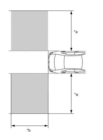
*a Within approximately 5.5 to 20 m (18.05 to 65.62 ft.) from Side of Vehicle (detection area changes according to vehicle speed) *b Within approximately 6 m (19.69 ft.) Behind Rear Bumper 
Detection Area Detection area
Vehicles in the following areas can be detected:
-
-
-
OPERATION OF OUTER REAR VIEW MIRROR INDICATOR AND RCTA BUZZER (BLIND SPOT MONITOR BUZZER) (Parking Support Alert [vehicles approaching from rear])
-
Initial check
-
When the blind spot monitor system is turned on with the power switch on (IG), the outer rear view mirror indicators on the outer mirror actuator assembly illuminate for 3 seconds and the RCTA buzzer (blind spot monitor buzzer) sounds for 1 second.
-
When the power switch is turned from off to on (IG) with the blind spot monitor system on, the outer rear view mirror indicators on the outer mirror actuator assembly illuminate for 3 seconds.
-
-
Operation for each function
-
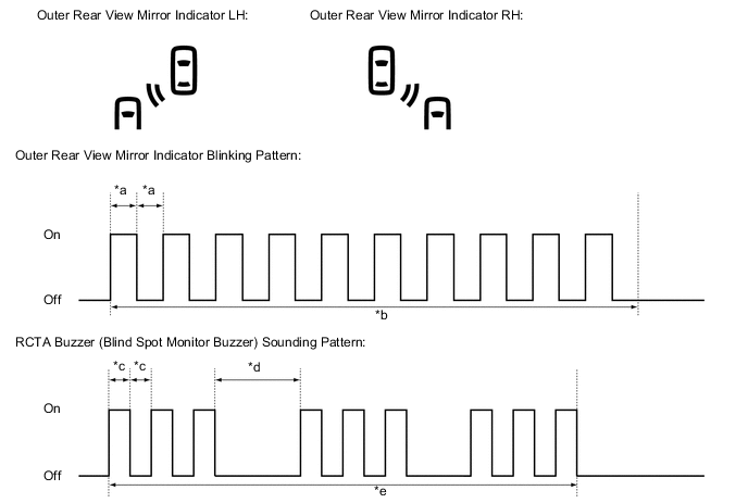
*a 0.125 Seconds *b 2.5 Seconds *c 0.1 Seconds *d 0.4 Seconds *e 2.3 Seconds - - Operation for RCTA function
-
When all of the operation conditions for the RCTA function are met, the outer rear view mirror indicators on the outer mirror actuator assembly blink for 2.5 seconds and the RCTA buzzer (blind spot monitor buzzer) sounds for 2.3 seconds as shown in the illustration.
-
-
-
-
OPERATION DESCRIPTION (Parking Support Alert [pedestrians behind vehicle])
-
Operation description of the rear camera detection function
-
Operation conditions:
-
The power switch on (IG).
-
The shift lever is in R.
-
-
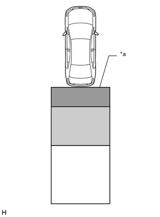
*a Detection Area 
Detection Area A Detection Area B 
Detection Area C Detection Area
Detection Area Buzzer Operation Pedestrian Detection Icon A Sounds repeatedly Blinks 3 times and then stays on B
-
When the vehicle is stationary: Sounds 3 times
-
When the vehicle is backing up: Sounds repeatedly
-
When the vehicle is stationary: Blinks 3 times
-
When the vehicle is backing up: Blinks 3 times and then stays on
C When it is determined that a pedestrian will enter area A within a few seconds: Sounds repeatedly When it is determined that a pedestrian will enter area A within a few seconds: Blinks 3 times and then stays on Tip:
-
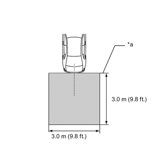
*a Edge of Bumper Absolute Detection Area Absolute Detection Area (3.0 m (9.8 ft.) from the edge of bumper, 3.0 m (9.8 ft.) wide
-
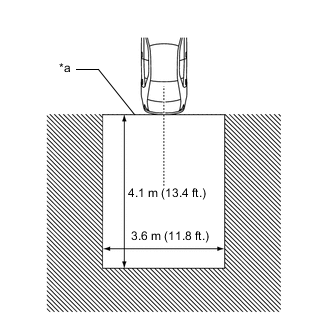
*a Edge of Bumper 
Absolute No Detection Area Absolute No Detection Area (4.1 m (13.4 ft.) from the edge of the bumper, 3.6 m (11.8 ft.) wide)
-
-
-