TELEMATICS SYSTEM(for G-BOOK) SYSTEM DESCRIPTION
-
TELEMATICS SYSTEM OUTLINE
-
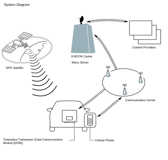
The telematics system is a telematics service that links the vehicle and G-BOOK network (provides information from the G-BOOK center or content providers).
-
To use the telematics system, it is necessary to connect the telematics transceiver (Data Communication Module [DCM]) to the navigation ECU.
Tech Tips
For vehicles with a telematics transceiver, the telematics system cannot be used over a "Wi-Fi" connection.
-
The user needs to follow the instructions on the multi-display assembly screen to start using the telematics system service after applying for the service at a dealership.
-
-
FUNCTION OF MAIN COMPONENTS
Component Function Map Light Assembly
-
Emergency Call Switch
When the emergency call switch is pressed, a switch signal is sent to the telematics transceiver. (When a manual maintenance check or manual emergency call is performed.) LED Indicator Light Green
-
Turns on for 5 seconds after the power switch is turned on (ACC).
-
Turns on when the system is under a service contract and operating normally.
-
Blinks during an emergency call.
-
Blinks during a manual maintenance check.
-
Turns off when the system is malfunctioning.
Red
-
Turns on for 5 seconds after the power switch is turned on (ACC).
-
Turns on when the telematics transceiver is not within the service area.
-
Blinks when an emergency call is made while the system is still malfunctioning.
-
Turns off when the system is operating normally.
-
Blinks when the mayday battery needs to be replaced.
-
Blinks in diagnostic mode to indicate a DTC.
Telephone Microphone Assembly
-
When the operator service is used: Sends the microphone voice signal to the radio receiver assembly.
-
When an emergency call is made: Sends the microphone voice signal to the telematics transceiver.
Roof Antenna Assembly Sends and receives the data and voice signals used for the G-BOOK through a communication network. Telematics Transceiver (Data Communication Module [DCM])
-
Uses the roof antenna assembly to send and receive the data and voice signals used for the G-BOOK through a communication network.
-
When the operator service is used: Sends the received voice signal to the radio receiver assembly.
-
When the operator service is used: Sends the sent voice signal from the radio receiver assembly to the roof antenna assembly.
-
When an emergency call is made: Sends the received voice signal to the vehicle speakers.
-
When an emergency call is made: Receives the sent voice signal from the telephone microphone assembly.
-
When an emergency call is made: Sends a mute signal to the stereo component amplifier assembly. (Mute function becomes active during the call.)
-
When an emergency call is made: Sends vehicle location information to the G-BOOK center.
-
When a warning occurs, the telematics transceiver receives a warning ON signal from the combination meter assembly via CAN communication and sends it to the G-BOOK center.
-
When the theft deterrent system is activated, the telematics transceiver sends information that the security horn has sounded to the G-BOOK center.
Mayday Battery (Back-up Battery)
-
When an automatic emergency call is performed, the mayday battery provides power to the telematics transceiver.
-
When a manual emergency call is made, the mayday battery is not used as the power source.
-
The mayday battery conducts a self-diagnosis every time the power switch is turned on (IG), and after an automatic emergency call or manual emergency call is made, and the result is sent to the telematics transceiver.
Navigation Antenna Assembly Receives GPS radio waves and sends them to the navigation ECU. Main Body ECU (Multiplex Network Body ECU) Sends a security horn sounding signal to the telematics transceiver when the theft deterrent system is activated. Radio Receiver Assembly
-
Sends and receives the data used for the G-BOOK to and from the telematics transceiver using a telematics data signal.
-
When the operator service is used: Sends the sent voice signal from the telephone microphone assembly to the telematics transceiver.
-
When the operator service is used: Sends the received voice signal from the telematics transceiver to the stereo component amplifier assembly using a MOST signal.
Navigation ECU
-
Sends and receives the data used for the G-BOOK to and from the telematics transceiver using a telematics data signal.
-
Sends vehicle location information to the telematics transceiver.
Stereo Component Amplifier Assembly Receives the received voice signal sent from the radio receiver assembly as a sound signal and outputs it as sound from the front No. 2 speaker assembly RH via the telematics transceiver. (When the operator service is used.) Airbag ECU Assembly Sends an activation signal to the telematics transceiver when airbags deploy. (An automatic emergency call is made.) Combination Meter Assembly Sends a warning signal to the telematics transceiver via CAN communication when a warning occurs. -
-
DEVICE USED FOR TELEMATICS SYSTEM COMMUNICATION
-
The telematics transceiver is used for data communication or emergency call service telephone calls and operator service telephone calls.
-
The hands-free function does not use the telematics transceiver. A user's "Bluetooth" compatible cellular phone needs to be used.
-
Perform the following if the device used for telematics system communication is replaced.
Tech Tips
-
If the navigation ECU or the telematics transceiver is replaced on vehicles that do not have a contract for the G-BOOK, perform vehicle contract setting.
-
If the navigation ECU or the telematics transceiver is replaced on vehicles that have a contract for the G-BOOK, perform the vehicle contract setting and the procedure to resume the G-BOOK to start the emergency call service.
-
-
-
G-BOOK ID OUTLINE
-
On this model, the radio receiver assembly functions as the G-BOOK device.
-
The radio receiver assembly has a serial number (G-BOOK ID) which can be used to determine the individual device when servicing.
-
-
MAYDAY ID OUTLINE
-
On this model, the telematics transceiver functions as the emergency call service device to perform emergency calls.
-
The radio receiver assembly has a serial number (mayday ID) which can be used to identify the individual device when servicing.
-
-
DATA COMMUNICATION MODULE (DCM) OUTLINE
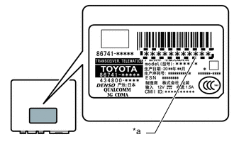
*a DCM ID
-
The G-BOOK device uses the telematics transceiver to provide access to the network service.
-
The telematics transceiver has a DCM ID (printed on the label attached to the telematics transceiver).
-
As is the case with cellular phones, the telematics transceiver has a phone number.
-
-
G-BOOK SUPPORT CENTER OUTLINE
-
The G-BOOK support center provides members with opportunities to ask questions and information necessary for troubleshooting.
G-BOOK Support Center Main Service Outline Answering questions about the telematics system Answers questions from customers about the telematics system Contracting or canceling the G-BOOK Performs procedures to make or cancel a contract for customers Confirming server or communication conditions Confirms the G-BOOK center condition Re-registering a G-BOOK device or telematics transceiver Performs procedures for re-registration when the G-BOOK device or telematics transceiver is replaced Answering questions about a manual maintenance check for the emergency call service Answers questions when a manual maintenance check for the emergency call service has not completed normally
-
-
COMMUNICATION SYSTEM
-
USB Outline
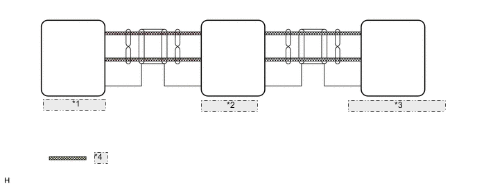
*1 Radio Receiver Assembly *2 Navigation ECU *3 Telematics Transceiver (Data Communication Module [DCM]) *4 USB Communication Line
-
Telematics system components communicate with each other via USB communication.
Tech Tips
If a short or open circuit occurs in a USB communication line, communication will be interrupted and the system will not operate normally.
-
-
MOST Network Outline
-
CAN Communication Outline
-
-
DIAGNOSTIC FUNCTION OUTLINE
-
The telematics system has a diagnostic function (the result will be displayed on the master unit or GTS).
-
-
DIAGNOSIS DISPLAY DETAILED DESCRIPTION
Tech Tips
This section contains a detailed description of displays in diagnostic mode.
-
Enter diagnostic mode.
-
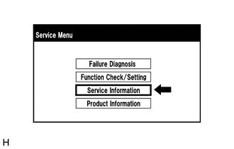
Select "Service Information" on the "Service Menu" screen.
-
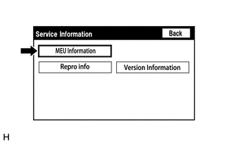
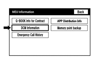
Select "MEU Information" from the "Service Information" screen.
-
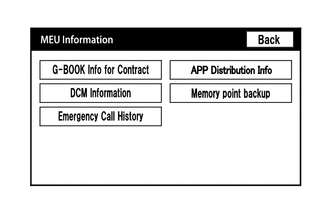
"MEU Information" screen.
Screen Description Display Content G-BOOK Info for Contract The G-BOOK ID, flag information, etc. are displayed. DCM Information The ID, contract information, maintenance check date, etc. which are related to the emergency call service are displayed. Emergency Call History The history (date and condition) of emergency calls is displayed.
-
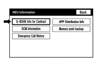
Select "G-BOOK Info for Contract" on the "MEU Information" screen.
-
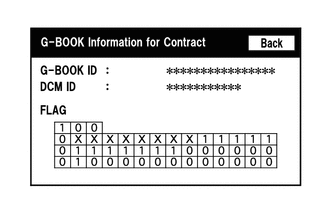
"G-BOOK Information for Contract" screen
Screen Description Display Content G-BOOK ID The G-BOOK ID of the navigation ECU is displayed. DCM ID The 11-digit serial number of the telematics transceiver is displayed. FLAG The G-BOOK contract flag or service flag of the navigation ECU is displayed. -
Service flag description
-

*a Example Flag information display
FLAG Information Display Content 1 Under service contract is in progress 0 No service contract X The G-BOOK service is suspended -
Flag information details
Tech Tips
The content shown below is an example. Content varies depending on the specification of the vehicle.
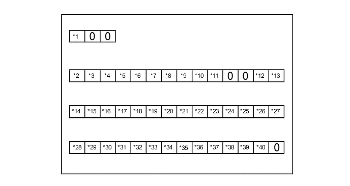
*1 G-BOOK contract flag *2 Vehicle stop position UP *3 Alarm report *4 Remote diagnosis *5 Remote customize *6 Remote warning *7 Remote immobiliser *8 Remote confirmation *9 Operation forgetting notification *10 Remote control *11 Gracenote service *12 Congestion forecast *13 Congestion forecast (time required) *14 Destination setting (set by G-BOOK) *15 DRGSCC *16 Help net *17 DCM voice call *18 diagnosis trigger function *19 FFD function *20 Map on demand *21 Probe *22 My request *23 DCMOSS call *24 ESPO *25 ETC charge display *26 POI Web search *27 Navi probe *28 Remote Monitoring *29 Remote diagnosis recorder *30 G Traffic information automatic acquisition service *31 Remote DDR *32 Screen display *33 Position upload *34 Full browser *35 Center route *36 Remote maintenance notice *37 Center voice recognition *38 Stolen Vehicle Tracking *39 Usage Based Insurance *40 eConnect Status Change Notification
-
-
Select "DCM Information" on the "MEU Information" screen.
-
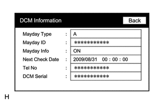
"DCM Information" screen
Screen Description Display Content Mayday Type The type of installed emergency call service device is displayed (on this model, "A" (airbag-linked type) is displayed). Mayday ID The ID of the installed emergency call service device is displayed. Mayday Info The emergency call service contract condition is displayed as follows:
-
ON: Contract has been made and membership has been registered
-
OFF: Contract has been made but membership has not been registered
-
NO CONT: Not contracted
Next Check Date The date on which the automatic maintenance check will be performed next is displayed. Tel No
-
The phone number of the telematics transceiver is displayed.
-
"NO DCM" is displayed when the telematics transceiver is not connected to the navigation ECU.
DCM Serial
-
The 11-digit serial number of the telematics transceiver is displayed (DCM ID).
-
"NO DCM" is displayed when the telematics transceiver is not connected to the navigation ECU.
-
-
-
VOICE RECOGNITION FUNCTION
-
There are two types of voice recognition; the voice recognition function uses voice recognition data stored in the onboard device. The other is communication based and uses voice recognition data sent from communication with the telematics transceiver (Data Communication Module [DCM]) as audio signals to be stored at the center.
-
Communication Based Voice Recognition
-
By performing the voice recognition process at the center, natural language input and interactive voice operations besides the specified commands can be performed.
-
-
-
MAYDAY BATTERY OUTLINE
-
As the mayday battery is a non-rechargeable (primary) battery, it cannot be recharged.
-
When it is time to replace the mayday battery, the emergency call switch red indicator will come on.
The telematics transceiver (Data Communication Module [DCM]) will also store a DTC.
Note
After an automatic emergency call is performed, the mayday battery must be replaced with a new one.
-
-
WARNING NOTIFICATION FUNCTION
Note
-
Before performing inspections or repairs which may cause warning messages or DTCs to occur, such as a simulation test or road test, it is necessary to activate warning notification restraint mode so that the G-BOOK center does not recognize the warnings as real ones.
-
Warning notification restraint mode can be entered by using the GTS or operating the multi-display assembly.
Tech Tips
The warning notification function sends a warning ON signal, received from the combination meter assembly via CAN communication, to the G-BOOK center using the G-BOOK device if a warning is displayed in the vehicle due to a vehicle malfunction.
-
Warning notification restraint mode
Tech Tips
To cancel warning notification restraint mode, turn the power switch off and on (IG) to display the service mode screen and cancel warning notification restraint mode.
-
Warning notification restraint mode (Using the GTS)
-
Turn the power switch off.
-
Connect the GTS to the DLC3.
-
Turn the power switch on (READY).
-
Turn the GTS on.
-
Enter the following menus: Powertrain / Engine and ECT / Trouble Codes.
Powertrain > Engine and ECT > Trouble Codes -
-
Warning notification restraint mode (Using the multi-display assembly)
-
Enter diagnostic mode of navigation system.
-
-
-