NAVIGATION SYSTEM Voice Guidance does not Function
WIRING DIAGRAM
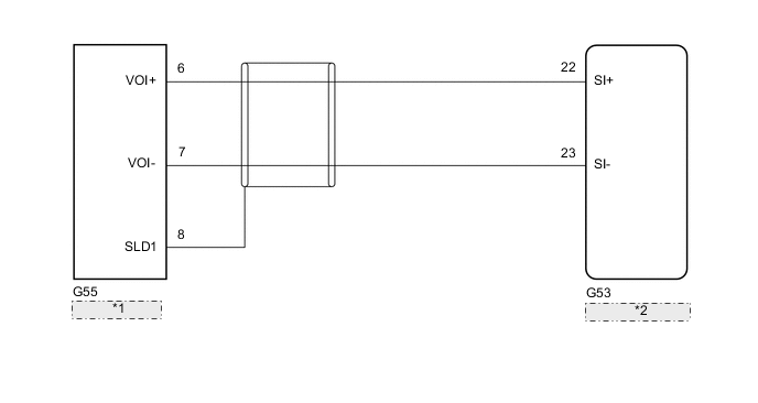
| *1 | Navigation ECU |
| *2 | Radio Receiver Assembly |
CAUTION / NOTICE / HINT
Note
When replacing the radio receiver assembly or navigation ECU, always replace it with a new one.
If a radio receiver assembly or navigation ECU which was installed to another vehicle is used, the following may occur:
-
A communication malfunction DTC may be stored.
-
The radio receiver assembly or navigation ECU may not operate normally.
PROCEDURE
-
CHECK VOICE GUIDANCE SETTING
-
Check that the voice guidance settings are not off.
OK Voice guidance settings are not off. Result Proceed to OK NG
NG 
CHANGE VOICE GUIDANCE SETTINGS TO ON
OK 
-
-
CHECK HARNESS AND CONNECTOR (RADIO RECEIVER ASSEMBLY - NAVIGATION ECU)
-
Disconnect the G53 radio receiver assembly connector.
-
Disconnect the G55 navigation ECU connector.
-
Measure the resistance according to the value(s) in the table below.
Standard Resistance Tester Connection Condition Specified Condition G53-22 (SI+) - G55-6 (VOI+) Always Below 1 Ω G53-23 (SI-) - G55-7 (VOI-) Always Below 1 Ω G53-22 (SI+) or G55-6 (VOI+) - Body ground Always 10 kΩ or higher G53-23 (SI-) or G55-7 (VOI-) - Body ground Always 10 kΩ or higher G55-8 (SLD1) - Body ground Always 10 kΩ or higher Result Proceed to OK NG
OK
PROCEED TO NEXT SUSPECTED AREA SHOWN IN PROBLEM SYMPTOMS TABLE Click here
NG
REPAIR OR REPLACE HARNESS OR CONNECTOR
-