NAVIGATION SYSTEM DTC CHECK / CLEAR
-
CHECK DTC (CHECK USING GTS)
-
Connect the GTS to the DLC3.
-
Turn the power switch on (IG) and wait for 90 seconds.
-
Turn the GTS on.
-
Enter the following menus: Body Electrical / Navigation System / Trouble Codes.
Body Electrical > Navigation System > Trouble Codes -
Check for DTCs, and then write them down.
-
Check the details of the DTC(s).
-
-
CLEAR DTC (CLEAR USING GTS)
-
Connect the GTS to the DLC3.
-
Turn the power switch on (IG) and wait for 90 seconds.
-
Turn the GTS on.
-
Enter the following menus: Body Electrical / Navigation System / Trouble Codes.
Body Electrical > Navigation System > Clear DTCs -
Clear the DTCs.
-
-
START DIAGNOSTIC MODE
Tech Tips
-
Illustrations may differ from the actual vehicle screen depending on the device settings and options. Therefore, some detailed areas may not be shown exactly the same as on the actual vehicle screen.
-
After the power switch is turned on (IG), check that the map is displayed before starting diagnostic mode. Otherwise, some items cannot be checked.
-
Start diagnostic mode using either of the 3 methods below.
-
Method 1:
-
Turn the power switch on (IG).
-
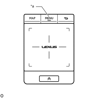
*a "MENU" Switch While pressing and holding the "MENU" switch, operate the light control switch: Off → Tail → Off → Tail → Off → Tail → Off.
-
Diagnostic mode starts and the "Service Menu" screen will be displayed. Service inspection starts automatically and the result will be displayed.
-
-
Method 2:
Note
-
If the operation fails and diagnostic mode cannot be entered, turn the multi-display screen display on and off once, and then perform the procedures listed below from the first step again. (Only turning the radio receiver assembly power supply on and off will not work.)
-
Do not touch the touch screen except when required.
-
Since the remote touch screen may recognize a pinch in/out or flick operation if operated with 2 fingers, always use 1 finger to operate the remote touch in diagnostic mode.
-
Turn the power switch on (IG).
-
Turn the multi-display screen display off.
-
Turn the radio receiver assembly power supply off.
-
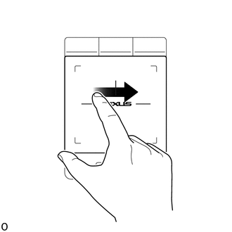
Perform the "left to right flick" operation on the touch pad 5 times as shown in the illustration.
-
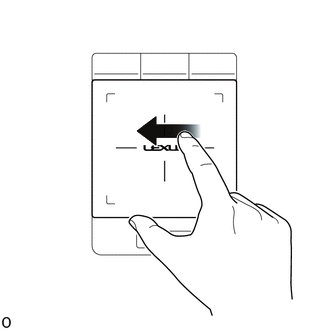
Perform the "right to left flick" operation on the touch pad 5 times as shown in the illustration.
Tech Tips
-
Complete the operation within 15 seconds of the first "left to right flick" operation.
-
Perform a flick operation at the center of the remote touch screen.
-
-
Diagnostic mode starts and the "Service Menu" screen will be displayed. Service inspection starts automatically and the result will be displayed.
-
-
Method 3:
-
Connect the GTS to the DLC3.
-
Turn the power switch on (IG).
-
Turn the GTS on.
-
Enter the following menus: Body Electrical / Navigation System / Utility / Map Information.
Body Electrical > Navigation System > UtilityTester Display Diagnostic Mode -
Diagnostic mode starts and the "Service Menu" screen will be displayed. Service inspection starts automatically and the result will be displayed.
-
-
Method 4:
Note
If the operation fails and diagnostic mode cannot be entered, turn the multi-display screen display on and off once, and then perform the procedures listed below from the first step again. (Only turning the radio receiver assembly power supply on and off will not work.)
-
Turn the power switch on (IG).
-
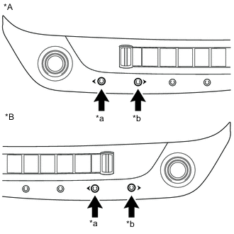
*A for LHD *B for RHD *a "<" switch *b ">" switch Turn the multi-display screen display off.
-
Turn the radio receiver assembly power supply off.
-
Press the ">" switch 5 times, and then press the "<" switch 5 times within 15 seconds.
-
Diagnostic mode starts and the "Service Menu" screen will be displayed. Service inspection starts automatically and the result will be displayed.
-
-
-
FAILURE DIAGNOSIS
-
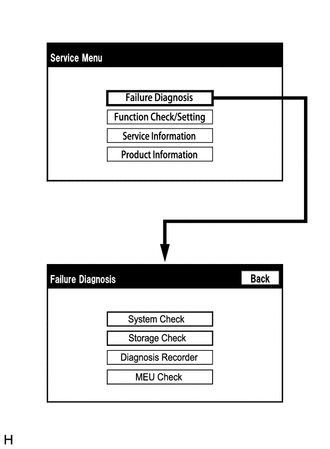
The "Failure Diagnosis" screen will be displayed by pressing the "Failure Diagnosis" switch on the "Service Menu" screen.
-
-
SYSTEM CHECK
-
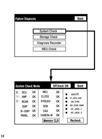
The "System Check Mode" screen will be displayed by selecting "System Check" on the "Failure Diagnosis" screen.
-
-
CHECK DTC (CHECK USING SYSTEM CHECK MODE SCREEN)
-
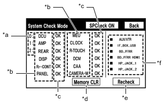
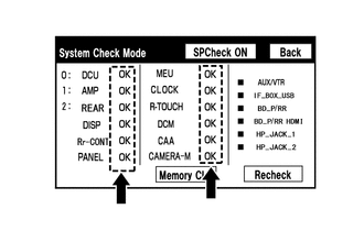
System check mode screen description
Screen Description Display Content *a: Node Position Number for Devices Connected to MOST Network MOST network node position numbers are provided for devices connected to the MOST network. *b: Device Name List No. 1
-
Device Name List No. 1 displays some of the devices that make up the navigation system.
-
The names of the components from Device Name List No. 1 are shown in the following table.
*c: Check Result
-
Result codes for all devices are displayed.
-
When "MOST" is displayed for the result, select "MOST" on the multi-display to display the "MOST Line Check" screen.
*d: Memory Clear
-
Present and history DTCs and registered connected device names are cleared.
-
Select "Memory CLR" for 3 seconds.
*e: Recheck
-
A system check will be performed again after the memory is cleared.
-
"Recheck" will dim during a system check.
*f: Device Name List No. 2
-
Device Name List No. 2 displays some of the devices that make up the navigation system.
-
The names of the components from Device Name List No. 2 are shown in the following table.
*b: Device Name List No. 1 Description Name Component Connection Method DCU Radio Receiver Assembly - AMP Stereo component amplifier assembly Communication line for MOST network REAR*1 Multi-display controller sub-assembly Communication line for MOST network DISP Multi-display Communication line for AVC-LAN Rr-CONT*2 Rear power seat switch Communication line for AVC-LAN PANEL Air conditioning control assembly (switch and volume) Communication line for AVC-LAN MEU Navigation ECU Communication line for USB CLOCK Clock assembly Local bus communication line R-TOUCH Remote operation controller assembly (remote touch) Local bus communication line DCM*3 DCM (telematics transceiver) Communication line for USB CAA*4 Television camera assembly Vehicle wire harness CAMERA-M*5 Parking assist ECU Connection line for GVIF *1: w/ Rear Seat Entertainment System
*2: w/ Rear Power Seat Control System
*3: w/ Telematics Transceiver (for G-BOOK)
*4: w/ Parking Assist Monitor System
*5: w/ Panoramic View Monitor System
*c: Check Result Description Result Meaning Action OK The device does not respond with a DTC. - MOST MOST communication error Perform "MOST Line Check" to check the connection of each device on the MOST network. DETAIL The device responds with a DTC. Look up the DTC in "Unit Check Mode". NCON The device was previously present, but does not respond in diagnostic mode. - Check power supply wire harness of the device.
- Check the AVC-LAN or MOST network of the device.
NRES The device responds in diagnostic mode, but gives no DTC information. - Check power supply wire harness of the device.
- Check the AVC-LAN or MOST network of the device.
*f: Device Name List No. 2 Description Name Component Connection Method AUX/VTR No. 1 stereo jack adapter assembly Vehicle wire harness IF-BOX_ USB No. 1 stereo jack adapter assembly Communication line for USB BD_P/RR* Disc player assembly Vehicle wire harness BD_P/RR HDMI* Disc player assembly Vehicle wire harness HP_JACK_1* Headphone terminal RH Vehicle wire harness HP_JACK_2* Headphone terminal LH Vehicle wire harness *: w/ Rear Seat Entertainment System
-
-
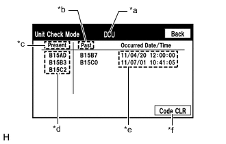
Unit check mode screen description
Screen Description Display Content *a: Device name Target device *b: History DTC Diagnostic memory results and stored DTCs are displayed. *c: Present DTC DTCs output in the service check are displayed. *d: DTC DTC (Diagnostic Trouble Code) *e: Timestamp The time and date of history DTCs are displayed. (The year is displayed in 2-digit format.) *f: Diagnosis clear switch Selecting "Code CLR" for 3 seconds clears the diagnostic memory data of the target device. (Both diagnostic system check result and the displayed data are cleared.) Tech Tips
-
This screen is updated once per second.
-
A maximum of 6 DTCs can be displayed for history and present DTCs.
-
-
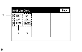
MOST line check screen description
Tech Tips
-
The inspection will be performed at the time the screen changes from "System Check Mode" to "MOST Line Check".
-
The master unit checks the connection of each device on the MOST network.
Screen Description Display Content *a: Node Position Number for Devices Connected to MOST Network MOST node position numbers are provided for devices connected to the MOST network. *b: Device Name List
-
Device Name List displays some of the devices that make up the navigation system.
-
The names of the components from Device Name List are shown in the following table.
*c: Check Result The master unit displays the check result on the screen based on the response information from each slave unit. *b: Device Name List Name Component DCU Radio receiver assembly AMP Stereo component amplifier assembly REAR* Multi-display controller sub-assembly *: w/ Rear Seat Entertainment System
*c: Check Result Result Meaning OK There was a response for the connection check during the MOST line check. NCON There was no response for the connection check during the MOST line check. Tech Tips
The device name and result will not be displayed if there is no system registration record and no response for the connection check during the MOST line check even if the device is connected to the MOST network.
-
-
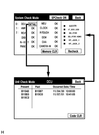
Read the system check result.
-
If the check result is "DETAIL", select the displayed check result to view the results on the "Unit Check Mode" screen and record them.
Note
A maximum of 6 DTCs can be displayed for history and present DTCs on the "Unit Check Mode" screen. Therefore, when 6 DTCs are displayed, troubleshoot those DTCs first and then check the "Unit Check Mode" screen again to see if any other DTCs are displayed.
Tech Tips
-
When all results are "OK", no DTCs are stored.
-
When "MOST" is displayed for the result, select "MOST" to display the "MOST Line Check" screen and check the MOST network.
-
Changing to the "MOST Line Check" screen is possible only when the MOST network is malfunctioning and "MOST" is displayed for the result.
-
If the MOST network had a malfunction in the past, DTCs will be displayed in the Memory column.
-
When "NCON" is displayed for all devices connected via the AVC-LAN, or when all device names are not displayed, check if there is a short circuit in the AVC-LAN or devices connected to the AVC-LAN. Repair or replace parts as necessary.
-
When proceeding to view the results of another device, select the "Back" switch to return to the "System Check Mode" screen. Repeat the above step to view the results of other devices.
-
-
Check the details of the DTC(s).
Note
The navigation system outputs DTCs for the following system. When DTCs other than those in Diagnostic Trouble Code Chart for the navigation system are output, refer to Diagnostic Trouble Code Chart for the relevant system.
System Proceed to Parking Assist Monitor System*1 Panoramic View Monitor System*2 Telematics System (for G-BOOK)*3 Rear Seat Entertainment System*4 *1: w/ Parking Assist Monitor System
*2: w/ Panoramic View Monitor System
*3: w/ Telematics Transceiver (for G-BOOK)
*4: w/ Rear Seat Entertainment System
-
-
-
DTC CLEAR/RECHECK (CLEAR USING SYSTEM CHECK MODE SCREEN)
-
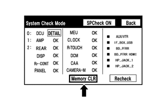
Clear DTCs
-
Select "Memory CLR" for 3 seconds.
-
Confirm that the check results are cleared.
Tech Tips
-
To clear the DTCs for a specific device, clear the DTCs using the "Unit Check Mode" screen.
-
When clearing DTCs using the "Unit Check Mode" screen, select "Code CLR" for 3 seconds.
-
-
-
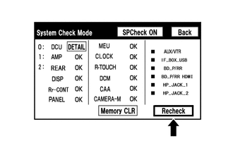
Recheck
-
Press the "Recheck" switch.
-
Confirm that all diagnostic codes are "OK" when the check results are displayed. If a result other than "OK" is displayed, perform troubleshooting again.
Tech Tips
When the DTCs are cleared using the "Unit Check Mode" screen, select "Back" to return to the "System Check Mode" screen and perform this operation.
-
-
-
FINISH DIAGNOSTIC MODE
-
Turn the power switch off.
-