ACTIVE NOISE CONTROL SYSTEM Power Source Circuit
DESCRIPTION
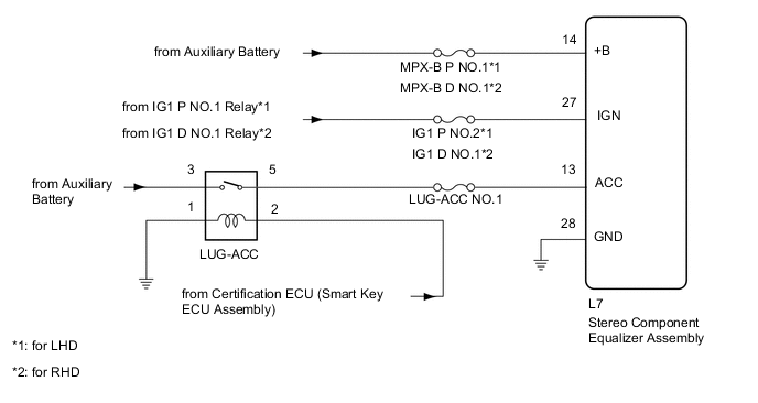
This circuit is the power source circuit for the stereo component equalizer assembly.
WIRING DIAGRAM
CAUTION / NOTICE / HINT
Note
Inspect the fuses and relays for circuits related to this system before performing the following procedure.
PROCEDURE
-
CHECK HARNESS AND CONNECTOR (STEREO COMPONENT EQUALIZER ASSEMBLY - BATTERY [+B, IGN] AND BODY GROUND)
-
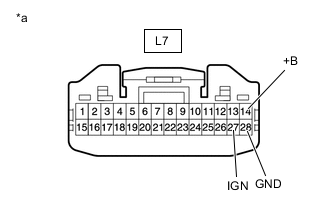
*a Front view of wire harness connector
(to Stereo Component Equalizer Assembly)
Disconnect the stereo component equalizer assembly connector.
-
Measure the voltage according to the value(s) in the table below.
Standard Voltage Tester Connection Condition Specified Condition L7-14 (+B) - Body ground Power switch off 11 to 14 V L7-27 (IGN) - Body ground Power switch on (IG) 11 to 14 V -
Measure the resistance according to the value(s) in the table below.
Standard Resistance Tester Connection Condition Specified Condition L7-28 (GND) - Body ground Always Below 1 Ω Result Proceed to OK NG
NG 
REPAIR OR REPLACE HARNESS OR CONNECTOR
OK 
-
-
CHECK HARNESS AND CONNECTOR (STEREO COMPONENT EQUALIZER ASSEMBLY - BATTERY [ACC] AND BODY GROUND)
-
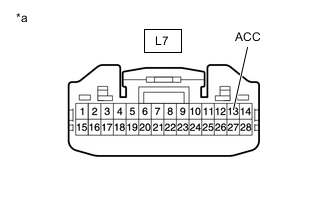
*a Front view of wire harness connector
(to Stereo Component Equalizer Assembly)
Disconnect the stereo component equalizer assembly connector.
-
Measure the voltage according to the value(s) in the table below.
Standard Voltage Tester Connection Switch Condition Specified Condition L7-13 (ACC) - Body ground Power switch on (ACC) 11 to 14 V Result Proceed to OK NG
OK
PROCEED TO NEXT SUSPECTED AREA SHOWN IN PROBLEM SYMPTOMS TABLE Click here
NG
GO TO ENTRY AND START SYSTEM (for Start Function) Click here
-