ACTIVE NOISE CONTROL SYSTEM TERMINALS OF ECU
-
CHECK STEREO COMPONENT EQUALIZER ASSEMBLY
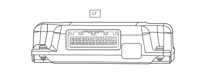
Terminal No. (Symbol) Wiring Color Terminal Description Condition Specified Condition L7-14 (+B) - L7-28 (GND) L - W-B Power source Power switch off 11 to 14 V L7-27 (IGN) - L7-28 (GND) B - W-B Power source (IG) Power switch on (IG) 11 to 14 V L7-13 (ACC) - L7-28 (GND) V - W-B Power source (ACC) Power switch on (ACC) 11 to 14 V L7-28 (GND) - Body ground W-B - Body ground Ground Always Below 1 Ω L7-7 (MC1+) - L7-28 (GND) W - W-B Active noise control microphone input signal No. 1 active noise control microphone tapped with finger Pulse generation L7-21 (MC1-) - L7-28 (GND) R - W-B Active noise control microphone input signal Always Below 1 Ω L7-6 (MC2+) - L7-28 (GND) B - W-B Active noise control microphone input signal No. 2 active noise control microphone tapped with finger Pulse generation L7-20 (MC2-) - L7-28 (GND) R - W-B Active noise control microphone input signal Always Below 1 Ω L7-5 (MC3+) - L7-28 (GND) LG - W-B Active noise control microphone input signal No. 3 active noise control microphone tapped with finger Pulse generation L7-19 (MC3-) - L7-28 (GND) R - W-B Active noise control microphone input signal Always Below 1 Ω L7-3 (NEI) - L7-28 (GND) L - W-B Engine pulse signal Idling with warm engine Pulse generation
(See waveform 1)
L7-12 (CH1+) - L7-28 (GND) W - W-B Active noise control microphone output signal Active noise control system operating Pulse generation L7-26 (CH1-) - L7-28 (GND) B - W-B Active noise control microphone output signal Active noise control system operating Pulse generation L7-11 (CH2+) - L7-28 (GND) R - W-B Active noise control microphone output signal Active noise control system operating Pulse generation L7-25 (CH2-) - L7-28 (GND) L - W-B Active noise control microphone output signal Active noise control system operating Pulse generation L7-10 (CH3+) - L7-28 (GND) G - W-B Active noise control microphone output signal Active noise control system operating Pulse generation L7-24 (CH3-) - L7-28 (GND) GR - W-B Active noise control microphone output signal Active noise control system operating Pulse generation L7-23 (ASG1) - L7-28 (GND) Shielded - W-B Shielded ground Always Below 1 Ω L7-17 (ACNT) - L7-28 (GND) B - W-B Active noise control system control signal Active noise control system not operating 4.5 V or higher Active noise control system operating Below 1 V L7-2 (ACK1) GR Serial communication (UART) signal - - L7-16 (ACK2) V Serial communication (UART) signal - - L7-1 (CANH) G CAN communication signal - - L7-15 (CANL) W CAN communication signal - -
-
Waveform 1
Tech Tips
The oscilloscope waveform shown in the illustration is an example for reference only. The waveform fluctuates according to engine speed.
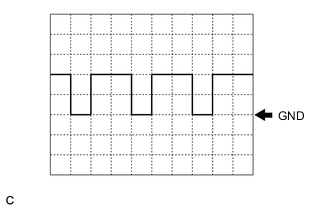
Item Condition Measurement terminal L7-3 (NEI) - L7-28 (GND) Tool setting 5 V/DIV., 20 ms./DIV. Vehicle condition Idling with warm engine
-
-
STEREO COMPONENT AMPLIFIER ASSEMBLY