REAR SEAT ENTERTAINMENT SYSTEM Sound Signal Circuit between Multi-display Controller and Head-phone Terminal
DESCRIPTION
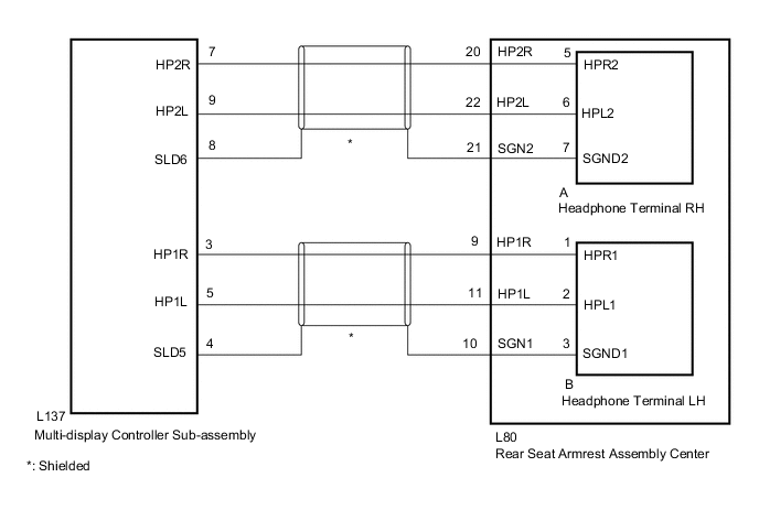
This is the sound signal circuit between the multi-display controller sub-assembly and each headphone terminal.
WIRING DIAGRAM
PROCEDURE
-
CHECK HARNESS AND CONNECTOR (MULTI-DISPLAY CONTROLLER SUB-ASSEMBLY - REAR SEAT ARMREST ASSEMBLY CENTER)
-
Disconnect the L137 multi-display controller sub-assembly connector.
-
Disconnect the L80 rear seat armrest assembly center connector.
-
Measure the resistance according to the value (s) in the table below.
Standard Resistance for RH Side Tester Connection Condition Specified Condition L137-7 (HP2R) - L80-20 (HP2R) Always Below 1 Ω L137-9 (HP2L) - L80-22 (HP2L) Always Below 1 Ω L137-8 (SLD6) - L80-21 (SGN2) Always Below 1 Ω L137-7 (HP2R) - Body ground Always Below 1 Ω L137-9 (HP2L) - Body ground Always Below 1 Ω L137-8 (SLD6) - Body ground Always Below 1 Ω for LH Side Tester Connection Condition Specified Condition L137-3 (HP1R) - L80-9 (HP1R) Always Below 1 Ω L137-5 (HP1L) - L80-11 (HP1L) Always Below 1 Ω L137-4 (SLD5) - L80-10 (SGN1) Always Below 1 Ω L137-3 (HP1R) - Body ground Always Below 1 Ω L137-5 (HP1L) - Body ground Always Below 1 Ω L137-4 (SLD5) - Body ground Always Below 1 Ω Result Proceed to OK NG
NG 
REPAIR OR REPLACE HARNESS OR CONNECTOR
OK 
-
-
INSPECT REAR SEAT ARMREST ASSEMBLY CENTER
-
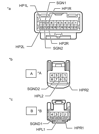
*A for RH Side *B for LH Side *a Component with harness connected
(to Wire Harness)
*b Component with harness connected
(to Headphone Terminal RH)
*c Component with harness connected
(to Headphone Terminal LH)
Remove the rear seat armrest assembly center.
-
Remove the headphone terminal.
-
Measure the resistance according to the value(s) in the table below.
Standard Resistance for RH Side Tester Connection Condition Specified Condition 20(HP2R) - A-5(HPR2) Always Below 1 Ω 22(HP2L) - A-6(HPL2) Always Below 1 Ω 21(SGN2) - A-7(SGND2) Always Below 1 Ω for LH Side Tester Connection Condition Specified Condition 9(HP1R) - B-1(HPR1) Always Below 1 Ω 11(HP1L) - B-2(HPL1) Always Below 1 Ω 10(SGN1) - B-3(SGND1) Always Below 1 Ω Result Proceed to OK NG
NG
REPLACE REAR SEAT ARMREST ASSEMBLY CENTER Click here
OK
-
-
CHECK HEADPHONE TERMINAL
-
Replace the malfunctioning headphone terminal with a new one or normally functioning headphone terminal.
-
Check if the same malfunction occurs again.
Result Result Proceed to The system returns to normal A Malfunction recurs B
A
END (HEADPHONE TERMINAL IS DEFECTIVE)
B
REPLACE MULTI-DISPLAY CONTROLLER SUB-ASSEMBLY Click here
-