REAR SEAT ENTERTAINMENT SYSTEM Illumination Circuit
DESCRIPTION
Power is supplied to the disc player assembly when the light control switch is in the tail or head position.
WIRING DIAGRAM
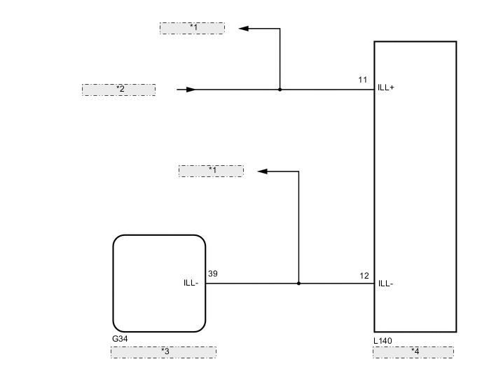
| *1 | to Other Systems |
| *2 | from PANEL P Relay |
| *3 | Combination Meter Assembly |
| *4 | Disc Player Assembly |
CAUTION / NOTICE / HINT
Note
Inspect the fuse for circuits related to this system before performing the following procedure.
PROCEDURE
-
CHECK METER / GAUGE SYSTEM
-
Check if the rheostat function operates normally.
OK The rheostat function operates normally. Result Proceed to OK NG
NG 
GO TO METER / GAUGE SYSTEM Click here
OK 
-
-
CHECK LIGHTING SYSTEM (INT)
-
Check if the instrument panel illumination comes on normally.
OK The instrument panel illumination comes on normally. Result Proceed to OK NG
NG
GO TO LIGHTING SYSTEM (INT) Click here
OK
-
-
CHECK HARNESS AND CONNECTOR (ILLUMINATION SIGNAL CIRCUIT)
-
Disconnect the L162 disc player assembly connector.
-
Measure the voltage according to the value(s) in the table below.
Standard Voltage Tester Connection Switch Condition Specified Condition L162-11 (ILL+) - Body ground Power switch on (IG), light control switch TAIL 11 to 14 V Result Proceed to OK NG
NG
REPAIR OR REPLACE HARNESS OR CONNECTOR
OK
-
-
CHECK HARNESS AND CONNECTOR (DISC PLAYER ASSEMBLY - COMBINATION METER ASSEMBLY)
-
Disconnect the L140 disc player assembly connector.
-
Disconnect the G34 combination meter assembly connector.
-
Measure the resistance according to the value(s) in the table below.
Standard Resistance Tester Connection Condition Specified Condition L140-12 (ILL-) - G34-39 (ILL-) Always Below 1 Ω Result Proceed to OK NG
OK
PROCEED TO NEXT SUSPECTED AREA SHOWN IN PROBLEM SYMPTOMS TABLE Click here
NG
REPAIR OR REPLACE HARNESS OR CONNECTOR
-