REAR SEAT ENTERTAINMENT SYSTEM Power Source Circuit
DESCRIPTION
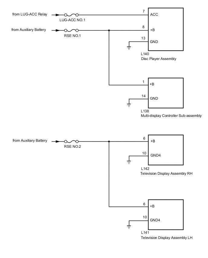
This is the power source circuit to operate the multi-display controller sub-assembly, television display assembly and disc player assembly.
WIRING DIAGRAM
CAUTION / NOTICE / HINT
Note
-
Depending on the parts that are replaced during vehicle inspection or maintenance, performing initialization, registration or calibration may be needed. Refer to Precaution for Rear Seat Entertainment System.
-
Inspect the fuses and relays for circuits related to this system before performing the following procedure.
PROCEDURE
-
CHECK OPERATION
-
Check which television display assembly does not operate.
Result Result Proceed to Television display assembly RH does not operate. A Television display assembly LH does not operate. B Disc player assembly does not operate. C Multi-display controller sub-assembly does not operate. D
B 
CHECK HARNESS AND CONNECTOR (TELEVISION DISPLAY ASSEMBLY LH - BATTERY AND BODY GROUND) Click here
C
CHECK HARNESS AND CONNECTOR (TELEVISION DISPLAY ASSEMBLY LH - BATTERY AND BODY GROUND) Click here
D
CHECK HARNESS AND CONNECTOR (TELEVISION DISPLAY ASSEMBLY LH - BATTERY AND BODY GROUND) Click here
A 
-
-
CHECK HARNESS AND CONNECTOR (TELEVISION DISPLAY ASSEMBLY RH - BATTERY AND BODY GROUND)
-
Disconnect the L142 television display assembly RH connector.
-
Measure the voltage according to the value(s) in the table below.
Standard Voltage Tester Connection Condition Specified Condition L142-6 (+B) - Body ground Power switch off 11 to 14 V -
Measure the resistance according to the value(s) in the table below.
Standard Resistance Tester Connection Condition Specified Condition L142-10 (GND4) - Body ground Always Below 1 Ω Result Proceed to OK NG
OK 
PROCEED TO NEXT SUSPECTED AREA SHOWN IN PROBLEM SYMPTOMS TABLE Click here
NG
REPAIR OR REPLACE HARNESS OR CONNECTOR
-
-
CHECK HARNESS AND CONNECTOR (TELEVISION DISPLAY ASSEMBLY LH - BATTERY AND BODY GROUND)
-
Disconnect the L141 television display assembly LH connector.
-
Measure the voltage according to the value(s) in the table below.
Standard Voltage Tester Connection Condition Specified Condition L141-6 (+B) - Body ground Power switch off 11 to 14 V -
Measure the resistance according to the value(s) in the table below.
Standard Resistance Tester Connection Condition Specified Condition L141-10 (GND4) - Body ground Always Below 1 Ω Result Proceed to OK NG
OK
PROCEED TO NEXT SUSPECTED AREA SHOWN IN PROBLEM SYMPTOMS TABLE Click here
NG
REPAIR OR REPLACE HARNESS OR CONNECTOR
-
-
CHECK HARNESS AND CONNECTOR (TELEVISION DISPLAY ASSEMBLY LH - BATTERY AND BODY GROUND)
-
Disconnect the L140 disc player assembly connector.
-
Measure the voltage according to the value(s) in the table below.
Standard Voltage Tester Connection Condition Specified Condition L140-8 (+B) - Body ground Power switch off 11 to 14 V L140-7 (ACC) - Body ground Power switch on (ACC) 11 to 14 V -
Measure the resistance according to the value(s) in the table below.
Standard Resistance Tester Connection Condition Specified Condition L140-13 (GND) - Body ground Always Below 1 Ω Result Proceed to OK NG
OK
PROCEED TO NEXT SUSPECTED AREA SHOWN IN PROBLEM SYMPTOMS TABLE Click here
NG
REPAIR OR REPLACE HARNESS OR CONNECTOR
-
-
CHECK HARNESS AND CONNECTOR (TELEVISION DISPLAY ASSEMBLY LH - BATTERY AND BODY GROUND)
-
Disconnect the L140 disc player assembly connector.
-
Measure the voltage according to the value(s) in the table below.
Standard Voltage Tester Connection Condition Specified Condition L138-1 (+B) - Body ground Power switch off 11 to 14 V -
Measure the resistance according to the value(s) in the table below.
Standard Resistance Tester Connection Condition Specified Condition L138-14 (GND) - Body ground Always Below 1 Ω Result Proceed to OK NG
OK
PROCEED TO NEXT SUSPECTED AREA SHOWN IN PROBLEM SYMPTOMS TABLE Click here
NG
REPAIR OR REPLACE HARNESS OR CONNECTOR
-