| DTC Code | DTC Name |
|---|---|
| B15DA | Rear Console Recognition Disconnected |
DESCRIPTION
The rear power seat switch (rear multi operation panel) and radio receiver assembly are connected by an AVC-LAN communication line. When an AVC-LAN communication error occurs between the radio receiver assembly and rear power seat switch (rear multi operation panel), these DTCs will be stored.
| DTC No. | Detection Item | DTC Detection Condition | Trouble Area |
|---|---|---|---|
| B15DA | Rear Console Recognition Disconnected | A device that is listed in the AVC-LAN connected device record of the master unit is missing. |
|
CAUTION / NOTICE / HINT
-
Inspect the fuse for circuits related to this system before performing the following procedure.
-
When replacing the radio receiver assembly, always replace it with a new one.
If a radio receiver assembly which was installed to another vehicle is used, the following may occur:
-
-
A communication malfunction DTC may be stored.
-
The radio receiver assembly may not operate normally.
-
Depending on the parts that are replaced during vehicle inspection or maintenance, performing initialization, registration or calibration may be needed. Refer to Precaution for Audio and Visual System.
PROCEDURE
- Click here
CHECK OPTIONAL COMPONENTS (INCLUDING ASSOCIATED WIRING)
-
Check for optional components.
-
Check that optional components (including associated wiring) which generate radio waves are not installed.
Result Result Proceed to Optional components (including associated wiring) are installed. A Optional components (including associated wiring) are not installed. B Tip:
-
Electrical noise from radio waves generated by optional components or the wiring for those components may affect AVC-LAN communication.
-
This DTC may be stored when an AVC-LAN communication error occurs due to electrical noise.
-
-
- AClick here
- BClick here
GO TO STEP 4
-
- Click here
REMOVE OPTIONAL COMPONENTS (INCLUDING ASSOCIATED WIRING)
-
Remove optional components (including associated wiring).
Note:Do not remove optional components or associated wiring without the permission of the customer.
Result Proceed to NEXT
- NEXTClick here
-
- Click here
CHECK DTC
-
Clear the DTCs.
- Body Electrical > Navigation System > Clear DTCs
-
-
-
Recheck for DTCs and check that no DTCs are output.
- Body Electrical > Navigation System > Trouble Codes
-
-
OK No DTCs are output. Result Proceed to OK NG
- OK
END (COMMUNICATION MALFUNCTION DUE TO NOISE)
- NGClick here
-
- Click here
CHECK HARNESS AND CONNECTOR (REAR SEAT ARMREST ASSEMBLY CENTER - BATTERY AND BODY GROUND)
-
Disconnect the L80 rear seat armrest assembly center connector.
-
Measure the resistance according to the value(s) in the table below.
Standard Resistance Tester Connection Condition Specified Condition L80-1 (E) - Body ground Always Below 1 Ω -
Measure the voltage according to the value(s) in the table below.
Standard Voltage Tester Connection Switch Condition Specified Condition L80-17 (B) - Body ground Power switch off 11 to 14 V L80-6 (ACC) - Body ground Power switch on (ACC) 11 to 14 V Result Proceed to OK NG
- OKClick here
- NG
REPAIR OR REPLACE HARNESS OR CONNECTOR
-
- Click here
CHECK REAR SEAT ARMREST ASSEMBLY CENTER
-
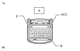
*a Front view of wire harness connector
(to Rear Power Seat Switch [Rear Multi Operation Panel])
Remove the rear power seat switch (rear multi operation panel).
-
Measure the resistance according to the value(s) in the table below.
Standard Resistance Tester Connection Condition Specified Condition A-1 (E) - Body ground Always Below 1 Ω -
Measure the voltage according to the value(s) in the table below.
Standard Voltage Tester Connection Condition Specified Condition A-12 (B) - Body ground Power switch off 11 to 14 V A-6 (ACC) - Body ground Power switch on (ACC) 11 to 14 V Result Proceed to OK NG
- OKClick here
- NG
REPLACE REAR SEAT ARMREST ASSEMBLY CENTERClick here
-
- Click here
CHECK HARNESS AND CONNECTOR (REAR SEAT ARMREST ASSEMBLY CENTER - AIR CONDITIONING CONTROL ASSEMBLY [SWITCH AND VOLUME])
-
Disconnect the L80 rear seat armrest assembly center connector.
-
Disconnect the G80 air conditioning control assembly (switch and volume) connector.
-
Measure the resistance according to the value(s) in the table below.
Standard Resistance Tester Connection Condition Specified Condition L80-12 (TX+) - G80-9 (TX+) Always Below 1 Ω L80-13 (TX-) - G80-10 (TX-) Always Below 1 Ω L80-12 (TX+) - Body ground Always 10 kΩ or higher L80-13 (TX-) - Body ground Always 10 kΩ or higher Result Proceed to OK NG
- OKClick here
- NG
REPAIR OR REPLACE HARNESS OR CONNECTOR
-
- Click here
INSPECT REAR SEAT ARMREST ASSEMBLY CENTER
-
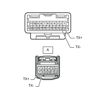
Remove the rear seat armrest assembly center.
-
Remove the rear power seat switch (rear multi operation panel).
-
Measure the resistance according to the value(s) in the table below.
Standard Resistance Tester Connection Condition Specified Condition 12 (TX+) - A-7 (TX-) Always Below 1 Ω 13 (TX-) - A-8 (TX-) Always Below 1 Ω A-7 (TX+) - A-8 (TX-) Always 10 kΩ or higher Result Proceed to OK NG
- OKClick here
- NG
REPLACE REAR SEAT ARMREST ASSEMBLY CENTERClick here
-
- Click here
CHECK REAR POWER SEAT SWITCH (REAR MULTI OPERATION PANEL)
-
Replace the rear power seat switch (rear multi operation panel) with a new or known good one.
-
Clear the DTCs.
- Body Electrical > Navigation System > Clear DTCs
-
-
-
Recheck for DTCs and check that no DTCs are output.
- Body Electrical > Navigation System > Trouble Codes
-
-
OK No DTCs are output. Result Proceed to OK NG
- OK
END (REAR POWER SEAT SWITCH [REAR MULTI OPERATION PANEL] IS DEFECTIVE)
- NGClick here
-
- Click here
CHECK AIR CONDITIONING CONTROL ASSEMBLY (SWITCH AND VOLUME)
-
Replace the air conditioning control assembly (switch and volume) with a new or known good one.
-
Clear the DTCs.
- Body Electrical > Navigation System > Clear DTCs
-
-
-
Recheck for DTCs and check that no DTCs are output.
- Body Electrical > Navigation System > Trouble Codes
-
-
OK No DTCs are output. Result Proceed to OK NG
- OK
END (AIR CONDITIONING CONTROL ASSEMBLY [SWITCH AND VOLUME] IS DEFECTIVE)
- NG
REPLACE RADIO RECEIVER ASSEMBLYClick here
-