AUDIO AND VISUAL SYSTEM Switch Lights of Remote Touch do not Illuminate
DESCRIPTION
Power is supplied to the remote touch illumination when the light control switch is in the tail or head position.
WIRING DIAGRAM
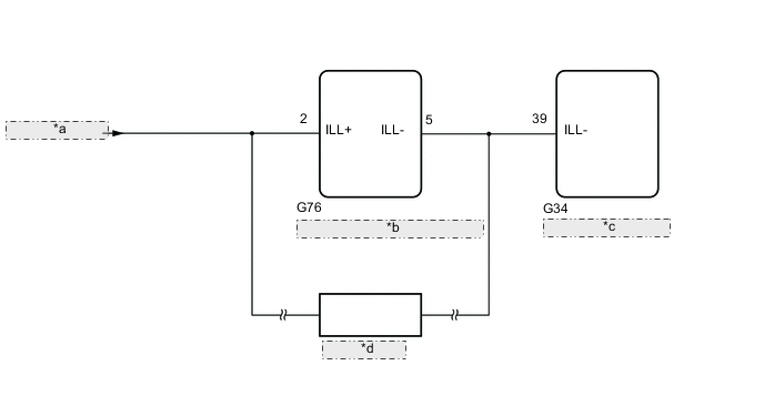
| *a | from PANEL P Relay |
| *b | Remote Operation Controller Assembly (Remote Touch) |
| *c | Combination Meter Assembly |
| *d | Other Systems |
PROCEDURE
-
CONFIRM SYMPTOMS
-
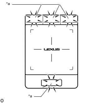
*a Switch Illumination Perform the following procedure and check the switch illumination again.
-
If the vehicle is in a bright area, move it to a dark area.
Tech Tips
When the vehicle is in a bright area, the switch illumination may not turn on due to the automatic dimmer function.
-
Set the rheostat to maximum brightness.
Tech Tips
If the brightness of the rheostat is set to low, switch illumination may not be recognized even when the switch illumination turns on.
-
If the light control switch is in the AUTO position, turn the switch to the tail or head position.
Tech Tips
If the light control switch is in the AUTO position, the switch illumination will not turn on unless the surrounding area is dark.
OK Switch illumination turns on.
Result Proceed to OK NG -
OK 
END
NG 
-
-
REMOTE TOUCH SELF CHECK (SWITCH ILLUMINATION CHECK)
-
Enter self-diagnostic mode.
-
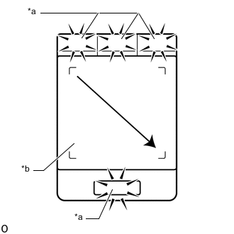
*a Switch Illumination *b Touch Screen Operate the remote touch screen diagonally from the upper left to the lower right and check that the brightness of the switch illumination changes.
Note
Since the remote touch screen may recognize a pinch in/out or flick operation if operated with 2 fingers, always use 1 finger to operate the remote touch in self-diagnostic mode.
OK Brightness changes according to touch screen operation. Result Proceed to OK NG
NG
REPLACE REMOTE OPERATION CONTROLLER ASSEMBLY (REMOTE TOUCH) Click here
OK
-
-
CHECK HARNESS AND CONNECTOR (ILLUMINATION SIGNAL CIRCUIT)
-
Disconnect the G76 remote operation controller assembly (remote touch) connector.
-
Measure the voltage according to the value(s) in the table below.
Standard Voltage Tester Connection Switch Condition Specified Condition G76-2 (ILL+) - Body ground Power switch on (IG)
Light control switch in tail or head position
11 to 14 V Result Proceed to OK NG
NG
REPAIR OR REPLACE HARNESS OR CONNECTOR
OK
-
-
CHECK HARNESS AND CONNECTOR (REMOTE OPERATION CONTROLLER ASSEMBLY [REMOTE TOUCH] - COMBINATION METER ASSEMBLY)
-
Disconnect the G76 remote operation controller assembly (remote touch) connector.
-
Disconnect the G34 combination meter assembly connector.
-
Measure the resistance according to the value(s) in the table below.
Standard Resistance Tester Connection Condition Specified Condition G76-5 (ILL-) - G34-39 (ILL-) Always Below 1 Ω Result Proceed to OK NG
OK
REPLACE REMOTE OPERATION CONTROLLER ASSEMBLY (REMOTE TOUCH) Click here
NG
REPAIR OR REPLACE HARNESS OR CONNECTOR
-