CAUTION / NOTICE / HINT
The necessary procedures (adjustment, calibration, initialization, or registration) that must be performed after parts are removed, installed, or replaced during the steering wheel assembly removal/installation are shown below.
| Replacement Part or Procedure | Necessary Procedure | Effect/Inoperative when not Performed | Link |
|---|---|---|---|
| Disconnect cable from negative auxiliary battery terminal | Memorize steering angle neutral point | LKA/LDA system (for Mono camera type) | for Stereo Camera type:Click here for Mono Camera type:Click here |
| Lane control system (for Stereo camera type) | |||
| Parking support brake system* | |||
| Pre-collision system (for Mono camera type) | |||
| Pre-collision system (for Stereo camera type) | |||
| Adaptive high beam system | |||
|
|||
| Variable gear ratio steering system | |||
| Parking assist monitor system | |||
| Panoramic view monitor system | |||
| Initialize rear door sunshade system | Rear door sunshade system | ||
| Initialize power trunk lid system | Power trunk lid system | ||
| Parts between the steering wheel and tires have been removed/installed, replaced or adjusted | Perform actuator angle neutral point calibration and initialization |
|
-
Use the same procedure for RHD and LHD vehicles.
-
The procedure listed below is for LHD vehicles.
PROCEDURE
- Click here
PRECAUTION
- Click here
ALIGN FRONT WHEELS FACING STRAIGHT AHEAD
- Click here
REMOVE HORN BUTTON ASSEMBLY
- Click here
REMOVE STEERING WHEEL ASSEMBLY
-
Disconnect each connector from the spiral cable with sensor sub-assembly.
-
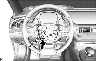
Disconnect the connector from the steering wheel heater control assembly.
-
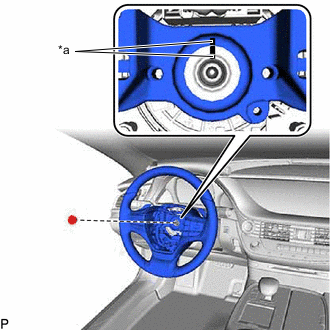
*a Matchmark Using a 10 mm hexagon socket wrench, remove the steering wheel assembly set bolt.
-
Put matchmarks on the steering wheel assembly and steering main shaft.
-
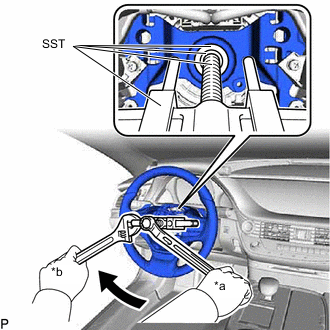
*a Turn *b Hold Using SST, remove the steering wheel assembly.
09950-40011 09957-04010 09950-50013 09951-05010 09952-05010 09953-05020 09954-05070 09950-60010 09951-00220 Note:Apply a small amount of grease to the threads and tip of SST (09953-05020) before use.
-
- Click here
REMOVE STEERING PAD SWITCH ASSEMBLY
- Click here
REMOVE NO. 1 STEERING WHEEL ORNAMENT
-
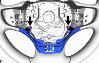
Remove the 2 screws.
-
Disengage the gaide pin to remove the No. 1 steering wheel ornament.
-
- Click here
REMOVE TRANSMISSION SHIFT SWITCH ASSEMBLY