CAUTION / NOTICE / HINT
-
Use the same procedure for RHD and LHD vehicles.
-
The procedure listed below is for LHD vehicles.
PROCEDURE
- Click here
INSTALL STEERING SLIDING WITH SHAFT YOKE SUB-ASSEMBLY (for 2WD)
-
w/o VGRS:
-
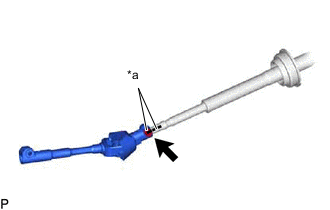
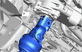
*a Matchmark Connect the steering sliding with shaft yoke sub-assembly to the No. 2 steering intermediate shaft assembly.
Note:Align the matchmarks on the steering sliding yoke sub-assembly and No. 2 steering intermediate shaft assembly.
-
Temporarily install the bolt.
-
-
w/ VGRS:
-
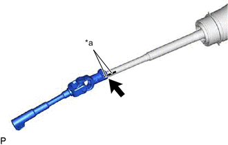
*a Matchmark Connect the steering sliding with shaft yoke sub-assembly to the steering actuator assembly.
Note:Align the matchmarks on the steering sliding with shaft yoke sub-assembly and steering actuator assembly.
-
Temporarily install the bolt.
-
-
- Click here
ALIGN FRONT WHEELS FACING STRAIGHT AHEAD
- Click here
INSTALL NO. 2 STEERING INTERMEDIATE SHAFT ASSEMBLY (w/o VGRS for 2WD)
-
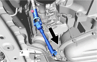
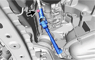
*a Matchmark Install the steering sliding with shaft yoke sub-assembly to the rack and pinion power steering gear assembly.
Note:Align the matchmarks on the steering sliding with shaft yoke sub-assembly and rack and pinion power steering gear assembly.
-
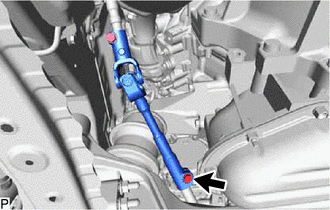
Install the bolt.
35.3 N*m 360 kgf*cm 26 ft.*lbf -
Tighten the clamp.
-
- Click here
INSTALL NO. 2 STEERING INTERMEDIATE SHAFT ASSEMBLY (for AWD)
-
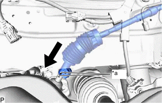
*a Matchmark Install the No. 2 steering intermediate shaft assembly to the rack and pinion power steering gear assembly.
Note:Align the matchmarks on the No. 2 steering intermediate shaft assembly and rack and pinion power steering gear assembly.
-

Install the bolt.
35.3 N*m 360 kgf*cm 26 ft.*lbf -
Tighten the clamp.
-
- Click here
INSTALL STEERING ACTUATOR ASSEMBLY (w/ VGRS)
- Click here
INSTALL STEERING COLUMN ASSEMBLY
-
w/o VGRS for 2WD:
-
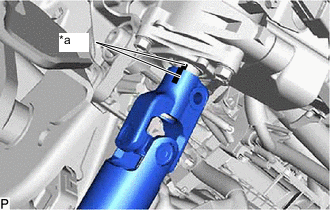
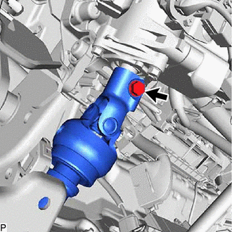
*a Matchmark Install the steering column assembly to the No. 2 steering intermediate shaft assembly.
Note:Align the matchmarks on the steering column assembly and No. 2 steering intermediate shaft assembly.
-
-
*a Matchmark for AWD:
-
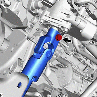
Install the steering column assembly to the No. 2 steering intermediate shaft assembly.
Note:Align the matchmarks on the steering column assembly and No. 2 steering intermediate shaft assembly.
-
-
w/ VGRS:
-
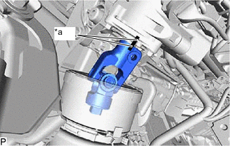
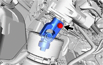
*a Matchmark Install the steering column assembly to the steering actuator assembly.
Note:Align the matchmarks on the steering column assembly and steering actuator assembly.
-
-
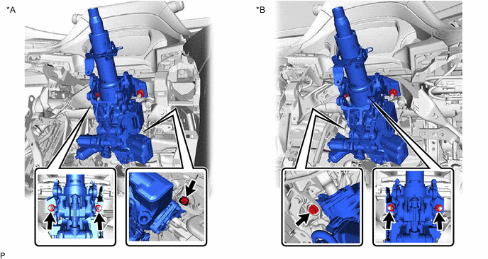
*A for LHD *B for RHD Install the steering column assembly with the 2 nuts and bolt.
nut 36 N*m 367 kgf*cm 27 ft.*lbf bolt 20 N*m 204 kgf*cm 15 ft.*lbf -
w/o VGRS for 2WD:
-
Install the bolt.
35.3 N*m 360 kgf*cm 26 ft.*lbf
-
-
for AWD:
-
Install the bolt.
35.3 N*m 360 kgf*cm 26 ft.*lbf
-
-
w/ VGRS:
-
Install the bolt.
35.3 N*m 360 kgf*cm 26 ft.*lbf
-
-
Connect each connector and engage each wire harness clamp to the steering column assembly.
-
Tighten the bolt.
35.3 N*m 360 kgf*cm 26 ft.*lbf
-
- Click here
INSTALL NO. 2 ENGINE UNDER COVER ASSEMBLY (for 2WD)
- Click here
INSTALL TRANSMISSION UNDER COVER (for 2WD)
- Click here
INSTALL FRONT WHEEL LH (for AWD)
- Click here
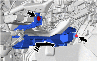
INSTALL NO. 1 HEATER TO REGISTER DUCT
-
Install the No. 1 heater to register duct with the 2 screws.
-
- Click here
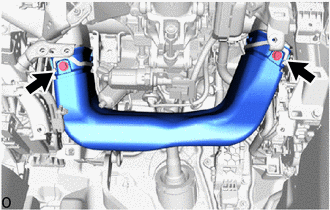
INSTALL NO. 1 AIR DUCT SUB-ASSEMBLY
-

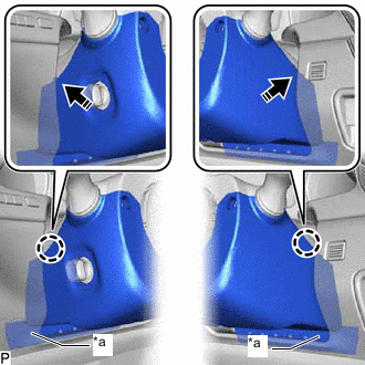
Install in this Direction Insert the No. 1 air duct sub-assembly in the direction of the arrow shown in the illustration to install it with the 2 bolts.
9.8 N*m 100 kgf*cm 87 in.*lbf
-
- Click here
INSTALL LOWER NO. 1 INSTRUMENT PANEL AIR BAG ASSEMBLY
- Click here
INSTALL TURN SIGNAL SWITCH ASSEMBLY WITH SPIRAL CABLE SUB-ASSEMBLY
Note:
-
Do not replace the spiral cable with sensor sub-assembly with the battery connected and the power switch on (IG).
-
Do not rotate the spiral cable with sensor sub-assembly without the steering wheel assembly installed, with the battery connected and the power switch on (IG).
-
Ensure that the steering wheel assembly is installed and aligned straight when inspecting the steering sensor.
-
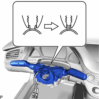
Using pliers, support the band clamp while loosened and set the turn signal switch assembly with spiral cable sub-assembly.
-
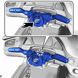
Install in this Direction Engage the claw to install the turn signal switch assembly with spiral cable sub-assembly to the steering column assembly as shown in the illustration.
-
Tighten the band clamp.
-
Connect each connector to the turn signal switch assembly with spiral cable sub-assembly.
-
- Click here
INSTALL UPPER STEERING COLUMN COVER
-
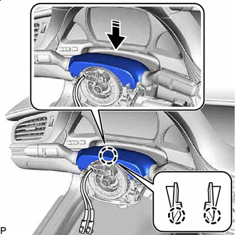
Install in this Direction Engage the claw to install the upper steering column cover.
-
Install in this Direction Attach the guides and claws in the direction indicated by the arrow in the illustration.
-
- Click here
INSTALL LOWER STEERING COLUMN COVER
-
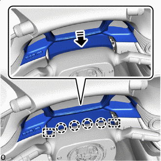
*a Felt Install in this Direction Insert the lower steering column cover in the direction indicated by the arrow.
Note:Do not damage the tilt and telescopic switch and felt.
-
Engage the 2 claws.
-
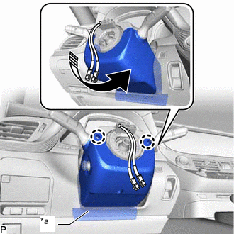
*a Felt Install in this Direction Engage the claw to install the lower steering column cover to the upper steering column cover.
Note:Do not damage the felt.
-
Install the 3 screws.
-
- Click here
ALIGN FRONT WHEELS FACING STRAIGHT AHEAD
- Click here
INSPECT AND ADJUST SPIRAL WITH SENSOR CABLE SUB-ASSEMBLY
- Click here
INSTALL STEERING WHEEL ASSEMBLY
- Click here
CHECK STEERING WHEEL CENTER POINT
- Click here
INSTALL HORN BUTTON ASSEMBLY
- Click here
CUSTOMIZE POWER TILT AND POWER TELESCOPIC STEERING COLUMN SYSTEM
-
Reset the auto tilt away function setting to the previous condition by changing the customize parameter.
-
- Click here
PERFORM VARIABLE GEAR RATIO STEERING SYSTEM CALIBRATION (w/ VGRS)
- Click here
PERFORM INITIALIZATION