STEERING COLUMN ASSEMBLY DISASSEMBLY

CAUTION / NOTICE / HINT
Note
-
Do not drop the steering lock actuator or upper bracket assembly, strike it with tools or subject it toimpacts.
-
If the steering lock actuator or upper bracket assembly is subjected to an impact, replace it with a newone.
PROCEDURE
-
REMOVE STEERING LOCK ACTUATOR OR UPPER BRACKET ASSEMBLY
-
Secure the steering column assembly in a vise between aluminum plates.
Note
-
Do not overtighten the vise.
-
Do not clamp the steering lock actuator or upper bracket assembly in the vise.
-
-
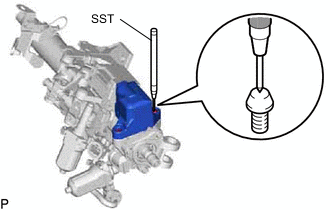
Using SST, strike a punch mark for drilling in the center of the steering lock set bolt.
- SST
- 09622-00010
Note
When striking the punch mark, in order to prevent impact force from being applied to the steering lock actuator or upper bracket assembly, do not use a normal center punch.
-
Using a drill, drill a hole in each steering lock set bolt and insert a screw extractor.
-
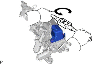
Using the screw extractor, remove the 2 steering lock set bolts and steering lock actuator or upper bracket assembly.
Note
Push in the screw extractor by hand, and do not strike it with tools, etc.
-
-
REMOVE MULTIPLEX TILT AND TELESCOPIC ECU
-
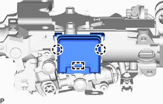
Disengage the 2 claws and guide to remove the multiplex tilt and telescopic ECU from the steering column assembly.
-