CAUTION / NOTICE / HINT
The necessary procedures (adjustment, calibration, initialization, or registration) that must be performed after parts are removed, installed, or replaced during the steering actuator assembly removal/installation are shown below.
| Replacement Part or Procedure | Necessary Procedure | Effect/Inoperative when not Performed | Link |
|---|---|---|---|
| Disconnect cable from negative auxiliary battery terminal | Memorize steering angle neutral point | LKA/LDA system (for Mono camera type) | for Stereo Camera type:Click here for Mono Camera type:Click here |
| Lane control system (for Stereo camera type) | |||
| Parking support brake system* | |||
| Pre-collision system (for Mono camera type) | |||
| Pre-collision system (for Stereo camera type) | |||
| Adaptive high beam system | |||
|
|||
| Variable gear ratio steering system | |||
| Parking assist monitor system | |||
| Panoramic view monitor system | |||
| Initialize rear door sunshade system | Rear door sunshade system | ||
| Initialize power trunk lid system | Power trunk lid system | ||
|
Perform actuator angle neutral point calibration and initialization |
|
-
Use the same procedure for RHD and LHD vehicles.
-
The procedure listed below is for LHD vehicles.
PROCEDURE
- Click here
PRECAUTION
- Click here
AIR SUSPENSION CONTROL PROHIBITED (w/ Air Suspension)
- Click here
REMOVE STEERING COLUMN ASSEMBLY
- Click here
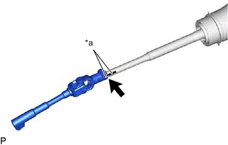
DISCONNECT STEERING SLIDING WITH SHAFT YOKE SUB-ASSEMBLY
-
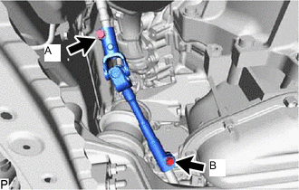
Loosen the bolt (A).
Note:Do not remove the bolt (A).
-
Remove the bolt (B).
-
*a Matchmark Slide the steering sliding with shaft yoke sub-assembly and put matchmarks on the steering sliding with shaft yoke sub-assembly and rack and pinion steering gear assembly.
-
Separate the steering sliding with shaft yoke sub-assembly from the rack and pinion steering gear assembly.
-
- Click here
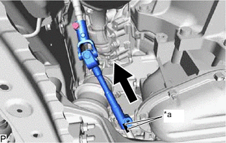
REMOVE STEERING ACTUATOR ASSEMBLY
-
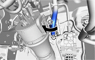
While pushing the claws on both sides of the connector, move the lock as shown in the illustration.
-
Disconnect the connector from the steering actuator assembly.
-
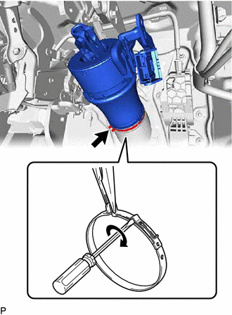
Using a screwdriver and needle-nose pliers, loosen the clamp as shown in the illustration.
-
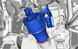
*a Matchmark Put matchmarks on the steering actuator assembly and No. 1 steering column hole cover sub-assembly.
-
Remove the steering actuator assembly with the steering sliding with shaft yoke sub-assembly from the vehicle.
-
- Click here
REMOVE STEERING SLIDING WITH SHAFT YOKE SUB-ASSEMBLY
-
*a Matchmark Put matchmarks on the steering sliding with shaft yoke sub-assembly and steering actuator assembly.
-
Remove the bolt.
-
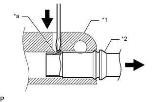
*1 Steering Sliding with Shaft Yoke Sub-assembly *2 Steering Actuator assembly *a Claw Using a screwdriver, disengage the claw and remove the steering sliding with shaft yoke sub-assembly from the steering actuator assembly.
Tip:Even if the claw is broken, the steering actuator assembly can be reused if the claw is removed.
-