VARIABLE GEAR RATIO STEERING SYSTEM TERMINALS OF ECU
-
CHECK VGRS ECU (FRONT STEERING CONTROL ECU)
Tech Tips
Inspect the connectors from the backside while they are connected.
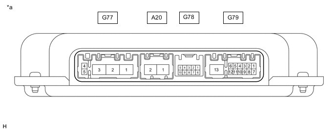
*a Component with harness connected
(VGRS ECU [Front Steering Control ECU])
- - Standard Terminal No. (Symbol) Wiring Color Terminal Description Condition Specified Condition A20-1 (PGND) - Body ground W-B - Body ground Ground Always Below 1 Ω A20-2 (PIG) - Body ground R - Body ground Power supply Always 11 to 14 V G77-1 (BMW) - G77-2 (BMV)/G77-3 (BMU) R - W/B Steering actuator motor signal (W phase) Power switch off Below 1 Ω G77-2 (BMV) - G77-3 (BMU)/G77-1 (BMW) W - B/R Steering actuator motor signal (V phase) Power switch off Below 1 Ω G77-3 (BMU) - G77-2 (BMV)/G77-1 (BMW) B - W/R Steering actuator motor signal (U phase) Power switch off Below 1 Ω G77-5 (SG) - Body ground BR - Body ground Steering actuator motor signal shielded ground Always Below 1 Ω G78-2 (LV) - Body ground Y - Body ground Power source for steering actuator lock Power switch on (IG) 11 to 14 V G78-3 (S1) - Body ground W - Body ground Steering actuator motor rotation angle sensor signal Power switch on (IG) Sine wave G78-5 (S2) - Body ground R - Body ground Steering actuator motor rotation angle sensor signal Power switch on (IG) Sine wave G78-6 (LG) - Body ground L - Body ground Steering actuator lock ground Power switch on (READY) 100 kΩ or higher G78-8 (RG) - Body ground G - Body ground Steering actuator resolver common ground Always Below 1 Ω G78-9 (RV) - Body ground B- Body ground Steering actuator resolver excitation output voltage Power switch on (IG) Sine wave G78-10 (SG2+) - Body ground Shielded - Body ground Shielded ground wire for steering actuator motor rotation angle sensor signal wire and control signal wire Always Below 1 Ω G79-1 (+BO) - Body ground LA-P - Body ground Steering sensor power supply line Always 11 to 14 V G79-2 (CNH2) - G79-8 (CNL2) P - W CAN communication Power switch off 54 to 69 Ω G79-3 (CNH1) - G79-9 (CNL1) BE - W CAN communication Power switch off 54 to 69 Ω G79-4 (IG) - Body ground LA-R - Body ground IG Power supply Power switch on (IG) 11 to 14 V G79-5 (SS1-) - Body ground R - Body ground Steering sensor signal Power switch on (READY) and steering wheel turned Pulse generation G79-6 (SS1+) - Body ground W - Body ground Steering sensor signal Power switch on (READY) and steering wheel turned Pulse generation G79-7 (+BI) - Body ground LA-L - Body ground ECU power supply Always 11 to 14 V G79-10 (CAN+) - G79-11 (CAN-) Y - W Local CAN communication Power switch off 54 to 69 Ω G79-13 (PGD2) - Body ground W-B - Body ground VGRS ECU (Front steering control ECU) ground Always Below 1 Ω