ELECTRIC PARKING BRAKE SYSTEM, Diagnostic DTC:C13A1
| DTC Code | DTC Name |
|---|---|
| C13A1 | Short Circuit in Power Source Circuit |
DESCRIPTION
C13A1 is stored if the power supply relay in the parking brake ECU assembly has a short circuit.
C13A1 is stored if the power switch is off and a voltage of 2.5 V or higher is applied to the IG terminal and an electric parking brake switch assembly malfunction or wire harness malfunction between the switch and ECU occurs.
| DTC No. | Detection Item | DTC Detection Condition | Trouble Area | Memory | Note |
|---|---|---|---|---|---|
| C13A1 | Short Circuit in Power Source Circuit |
|
|
Yes | An electric parking brake system malfunction is displayed on the multi-information display. |
| Vehicle Condition | |||
| Pattern 1 | Pattern 2 | ||
| Diagnosis Condition | Electric parking brake switch assembly is operated to lock side with power switch off | ○ | - |
| Power switch on (IG) | - | ○ | |
| Malfunction Status | Short in parking brake ECU assembly internal power source relay | ○ | ○ |
| Detection Time | Approximately 60 seconds | Approximately 60 seconds | |
| Trip Count | 1 trip | 1 trip | |
Tech Tips
If the conditions match either of these patterns, a DTC will be output.
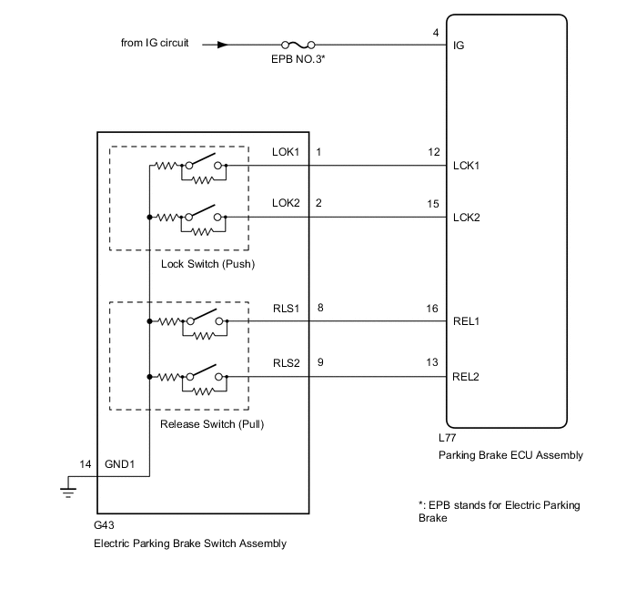
WIRING DIAGRAM
CAUTION / NOTICE / HINT
Note
-
Inspect the fuses for circuits related to this system before performing the following inspection procedure.
-
The electric parking brake may still operate up to 20 seconds after the power switch is turned off. Before disconnecting connectors or fuses, turn the power switch off and wait 20 seconds or more.
-
If the parking brake ECU assembly is replaced, perform the "Reset Memory" and "Acquire Tension Sensor Zero Point" procedures
PROCEDURE
-
CHECK HARNESS AND CONNECTOR (PARKING BRAKE ECU ASSEMBLY - IG POWER SOURCE CIRCUIT)
-
Turn the power switch off.
-
Disconnect the parking brake ECU assembly connector.
-
Measure the voltage according to the value(s) in the table below.
Standard Voltage Tester Connection Switch Condition Specified Condition L77-4 (IG) - Body ground Power switch off Below 2.5 V Result Proceed to OK NG
NG 
REPAIR IG POWER SOURCE CIRCUIT
OK 
-
-
INSPECT ELECTRIC PARKING BRAKE SWITCH ASSEMBLY
-
Inspect the electric parking brake switch assembly.
Result Proceed to OK NG
NG
REPLACE ELECTRIC PARKING BRAKE SWITCH ASSEMBLY Click here
OK
-
-
CHECK HARNESS AND CONNECTOR (PARKING BRAKE ECU ASSEMBLY - ELECTRIC PARKING BRAKE SWITCH ASSEMBLY)
-
Turn the power switch off.
-
Disconnect the G43 electric parking brake switch assembly connector.
-
Disconnect the parking brake ECU assembly connector.
-
Measure the resistance according to the value(s) in the table below.
Standard Resistance Tester Connection Condition Specified Condition L77-12 (LCK1) - Body ground Always 10 kΩ or higher L77-13 (REL2) - Body ground Always 10 kΩ or higher L77-15 (LCK2) - Body ground Always 10 kΩ or higher L77-16 (REL1) - Body ground Always 10 kΩ or higher Result Proceed to OK NG
OK
REPLACE PARKING BRAKE ECU ASSEMBLY Click here
NG
REPAIR OR REPLACE HARNESS OR CONNECTOR
-