BRAKE PEDAL(for LHD) REMOVAL
CAUTION / NOTICE / HINT
The necessary procedures (adjustment, calibration, initialization, or registration) that must be performed after parts are removed, installed, or replaced during brake pedal support assembly removal/installation are shown below.
| Replaced Part or Performed Procedure | Necessary Procedure | Effect/Inoperative Function when Necessary Procedure not Performed | Link |
|---|---|---|---|
| Auxiliary battery terminal is disconnected/reconnected | Memorize steering angle neutral point | LKA/LDA system (for Mono camera type) | for Stereo Camera type: Click here for Mono Camera type: Click here |
| Lane control system (for Stereo camera type) | |||
| Parking support brake system* | |||
| Pre-collision system (for Stereo camera type) | |||
| Pre-collision system (for Mono camera type) | |||
| Adaptive high beam system | |||
Lighting system (EXT) |
|||
| Variable gear ratio steering system | |||
| Parking assist monitor system | |||
| Panoramic view monitor system | |||
| Initialize rear door sunshade system | Rear door sunshade system | ||
| Initialize power trunk lid system | Power trunk lid system | ||
|
|
|
for Initialization: Click here for Calibration: Click here |
Click here Click here
PROCEDURE
-
REMOVE STEERING COLUMN ASSEMBLY
-
DISCONNECT BRAKE PEDAL SUPPORT ASSEMBLY
-
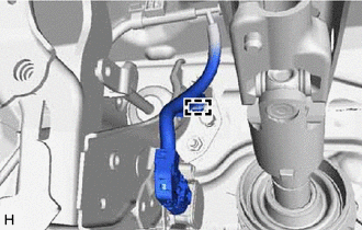
Disconnect the wire harness clamp from the brake pedal support assembly.
-
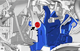
Remove the bolt and disconnect the brake pedal support assembly from the instrument panel reinforcement assembly.
-
-
REMOVE INSTRUMENT PANEL REINFORCEMENT ASSEMBLY
-
REMOVE BRAKE PEDAL STROKE SENSOR ASSEMBLY
-
REMOVE BRAKE PEDAL RETURN SPRING
-
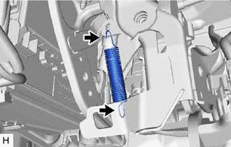
Remove the brake pedal return spring from the brake pedal support assembly.
-
-
REMOVE STOP LIGHT SWITCH ASSEMBLY
-
REMOVE STOP LIGHT SWITCH MOUNTING ADJUSTER
-
REMOVE PUSH ROD PIN
-
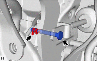
Remove the clip and push rod pin.
-
-
REMOVE BRAKE PEDAL SUPPORT ASSEMBLY
-
Remove the 2 clips from the brake pedal support assembly.
-
Remove the 4 nuts and brake pedal support assembly.
-
-
REMOVE BRAKE PEDAL PAD
-
Remove the brake pedal pad from the brake pedal support assembly.
-