CAUTION / NOTICE / HINT
The necessary procedures (adjustment, calibration, initialization, or registration) that must be performed after parts are removed, installed, or replaced during yaw rate sensor assembly removal/installation are shown below.
| Replaced Part or Performed Procedure | Necessary Procedure | Effect/Inoperative Function when Necessary Procedure not Performed | Link |
|---|---|---|---|
| Yaw rate sensor |
|
|
for Initialization:Click here for Calibration:Click here |
|
Perform learning for the yaw rate and G sensor |
|
PROCEDURE
- Click here
REMOVE CONSOLE BOX ASSEMBLY
- Click here
REMOVE NO. 1 CONSOLE BOX MOUNTING BRACKET
-
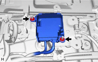
Remove the 2 nuts and pedestrian detection ECU assembly.
-
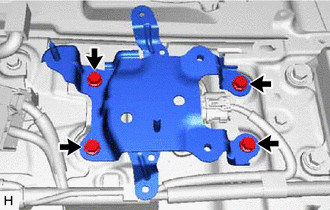
Remove the 4 bolts and No. 1 console box mounting bracket.
-
- Click here
REMOVE YAW RATE SENSOR
-
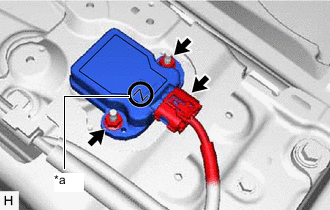
*a Identification Number Disconnect the connector from the yaw rate sensor.
-
Remove the 2 nuts and yaw rate sensor assembly.
Note:
-
Make sure the yaw rate sensor's identification number is Z.
-
Do not drop the yaw rate sensor. If it is dropped, do not use it.
-
-