Click here
PROCEDURE
- Click here
INSPECT ABS MOTOR RELAY
-
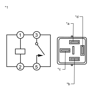
*1 ABS Motor Relay (ABS MTR NO. 1 or ABS MTR NO. 2 relay) *a MR1 or MR2 Terminal *b R1- or R2- Terminal *c BM1 or BM2 Terminal *d +BM1 or +BM2 Terminal Remove the ABS motor relay (ABS MTR NO. 1 and ABS MTR NO. 2 relays).
-
Check both the relay case and the terminal for deformation and corrosion.
OK No deformation or corrosion. -
Measure the resistance according to the value(s) in the table below.
Standard Resistance Table 1. for ABS MTR NO. 1 relay Tester Connection Condition Specified Condition 3 (BM1) - 5 (+BM1) Voltage is not applied between terminals 1 (MR1) and 2 (R1-) 10 kΩ or higher 3 (BM1) - 5 (+BM1) Voltage is applied between terminals 1 (MR1) and 2 (R1-) Below 1 Ω Table 2. for ABS MTR NO. 2 relay Tester Connection Condition Specified Condition 3 (BM2) - 5 (+BM2) Voltage is not applied between terminals 1 (MR2) and 2 (R2-) 10 kΩ or higher 3 (BM2) - 5 (+BM2) Voltage is applied between terminals 1 (MR2) and 2 (R2-) Below 1 Ω If the result is not as specified, replace the ABS motor relay (ABS MTR NO. 1 and/or ABS MTR NO. 2 relay).
-