ELECTRONICALLY CONTROLLED BRAKE SYSTEM Abnormal Brake Pedal Response on First Depression
DESCRIPTION
If the vehicle has been stopped without opening or closing the driver door for a long period of time, the electronically controlled brake system will not be ready and sufficient fluid pressure may not be stored in the accumulator. In this case, the brake pedal response may not be the same as usual the first time the brake pedal is depressed. This is not a malfunction.
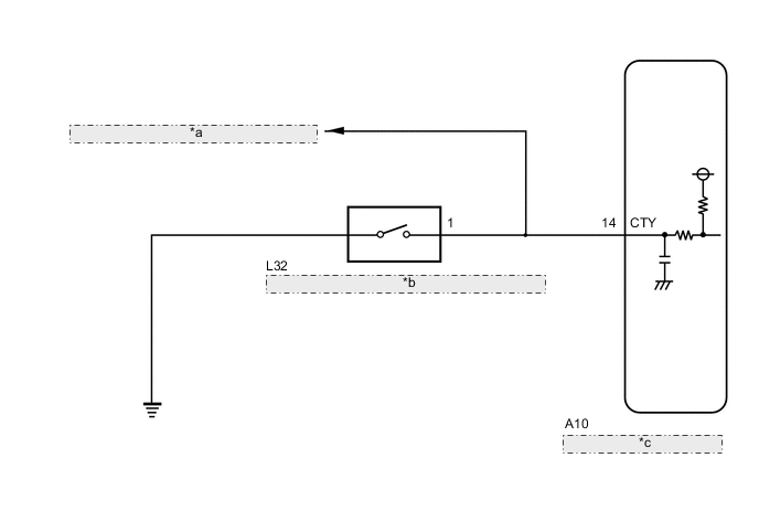
WIRING DIAGRAM
Figure 1. for LHD:

| *a | to Main Body ECU (Multiplex Network Body ECU) |
| *b | Front Door Courtesy Light Switch Assembly LH |
| *c | Skid Control ECU Assembly |
Figure 2. for RHD:
| *a | to Main Body ECU (Multiplex Network Body ECU) |
| *b | Front Door Courtesy Light Switch Assembly LH |
| *c | Skid Control ECU Assembly |
CAUTION / NOTICE / HINT
Note
When replacing the skid control ECU assembly, perform initialization and calibration of the linear solenoid valve.
PROCEDURE
-
BRAKE PROBLEM CHECK
-
Check the conditions at the time the problem occurred.
-
Whether a warning light illuminated or the buzzer sounded.
-
The number of times the power switch was turned on (IG) since the latest symptom occurred.
-
Frequency of the symptom.
Result Proceed to NEXT -
NEXT 
-
-
CHECK DTC
-
Clear the DTCs.
Chassis > ABS/VSC/TRC > Clear DTCs -
Turn the power switch off.
-
Turn the power switch on (IG).
-
Check the DTCs (electronically controlled brake system) that are output.
Chassis > ABS/VSC/TRC > Trouble CodesResult Result Proceed to DTCs C1391 and C1256 are not output. A DTCs C1391 and/or C1256 are output. B
B 
REPAIR CIRCUITS INDICATED BY OUTPUT DTCS Click here
A
-
-
CHECK VEHICLE
-
Turn the power switch off.
-
Depress the brake pedal within 2 minutes of opening the driver door and check the response of the brake pedal.
-
Release the brake pedal and wait for 2 minutes without depressing the brake pedal, opening or closing the driver door or operating the power switch.
-
After 2 seconds or more have elapsed, depress the brake pedal and check that the first depression response is different to successive depression responses.
Tech Tips
Compare the response of the brake pedal when the system is in sleep mode and when the stroke simulator is operating.
Result Result Proceed to The response of the brake pedal does not change. A The response of the brake pedal changed. B
B
END
A
-
-
INSPECT FRONT DOOR COURTESY LIGHT SWITC ASSEMBLY
-
Set the interior light door switch to ON and check that the map light assembly illuminates, then set the interior light door switch to DOOR.
-
Check that the map light assembly illuminates when the driver door is opened.
OK The map light assembly illuminates when the driver door is opened. Result Proceed to OK NG
NG
INSPECT LIGHTING SYSTEM (COURTESY LIGHT SWITCH CIRCUIT) Click here
OK
-
-
CHECK HARNESS AND CONNECTOR (CTY TERMINAL)
-
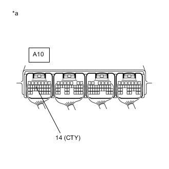
*a Component with harness connected
(Skid Control ECU Assembly)
Measure the voltage and waveform according to the value(s) in the table below.
Standard Voltage Tester Connection Condition Specified Condition A10-14 (CTY) - Body ground Driver door open Below 1 V A10-14 (CTY) - Body ground Driver door closed Pulse generation (waveform 1)
-
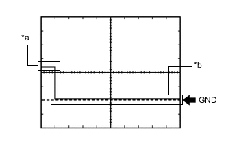
*a Driver door closed *b Driver door open Waveform 1 (Reference)
Item Content Tester Connection A10-14 (CTY) - Body ground Tool Setting 5 V/DIV., 10 ms./DIV. Vehicle Condition Driver door closed → open
Result Proceed to OK NG -
OK
REPLACE SKID CONTROL ECU ASSEMBLY for LHD: Click here
REPLACE SKID CONTROL ECU ASSEMBLY for RHD: Click hereNG
REPAIR OR REPLACE HARNESS OR CONNECTOR (CTY CIRCUIT)
-