ELECTRONICALLY CONTROLLED BRAKE SYSTEM Brake Hold Standby Indicator Light Circuit
DESCRIPTION
The brake hold standby indicator light turns on if brake hold control is possible when the following conditions required for operation standby are met and the brake hold switch is turned on while the power switch is on (IG).
-
Conditions required for operation standby:
-
The driver side door is closed.
-
The driver side seat belt is fastened.
-
The system is normal.
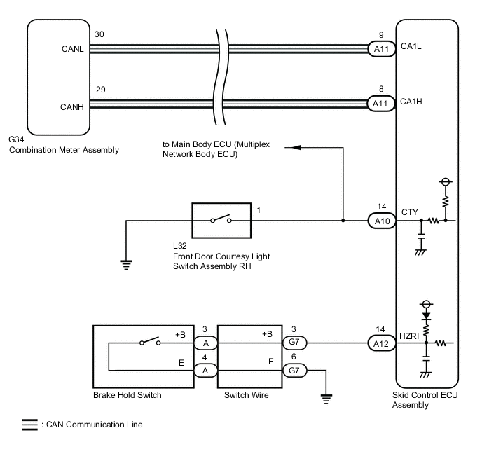
WIRING DIAGRAM
Figure 1. for LHD:
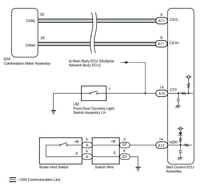
Figure 2. for RHD:
CAUTION / NOTICE / HINT
Note
When replacing the skid control ECU assembly, perform initialization and calibration of the linear solenoid valve.
PROCEDURE
-
PRE-CHECK
-
If the brake hold standby indicator light does not illuminate even though the brake hold switch is pushed, check that the brake hold function operation conditions are met.
-
The driver side door is closed.
-
The driver side seat belt is fastened.
-
The system is normal.
Tech Tips
If a malfunction occurs in one of the following systems, the brake hold operated indicator light will blink. If this occurs, perform troubleshooting on the malfunctioning system.
-
Brake system
-
Electric parking brake system
-
Hybrid control system
Result Proceed to NEXT -
NEXT 
-
-
CHECK CAN COMMUNICATION SYSTEM
-
Check if CAN communication system DTCs are output.
Result Result Proceed to DTCs are not output. A DTCs are output. B
B 
INSPECT CAN COMMUNICATION SYSTEM Click here
A
-
-
PERFORM ACTIVE TEST USING GTS (BRAKE HOLD STANDBY INDICATOR LIGHT)
-
Connect the GTS to the DLC3.
-
Turn the power switch on (IG).
-
Select the Active Test on the GTS.
Chassis > ABS/VSC/TRC > Active TestTester Display Measurement Item Control Range Diagnostic Note BH Standby Light Brake hold standby indicator light Indicator light ON/OFF Observe combination meter assembly
Chassis > ABS/VSC/TRC > Active TestTester Display BH Standby Light -
Select the Data List on the GTS.
Chassis > ABS/VSC/TRC > Data ListTester Display Measurement Item Range Normal Condition Diagnostic Note BH Standby Light Brake hold standby indicator light ON or OFF ON: Indicator light on
OFF: Indicator light off
-
Chassis > ABS/VSC/TRC > Data ListTester Display BH Standby Light -
Check the operating condition of the brake hold standby indicator light when operating it using the GTS.
Result Result Proceed to Brake hold standby indicator light in the Data List does not change using the Active Test. A Brake hold standby indicator light in the Data List turns ON/OFF using the Active Test. B
A
REPLACE SKID CONTROL ECU ASSEMBLY for LHD: Click here
REPLACE SKID CONTROL ECU ASSEMBLY for RHD: Click hereB
-
-
INSPECT COMBINATION METER ASSEMBLY
-
Turn the power switch off.
-
Perform the Active Test of the combination meter assembly (meter CPU) using the GTS.
for Sport Package:
Body Electrical > Combination Meter > Active TestTester Display Brake Hold Indicator except Sport Package:
Body Electrical > Combination Meter > Active TestTester Display Multi Display Default Screen -
Check the combination meter assembly.
OK for Sport Package The brake hold standby indicator light turns on or off in accordance with the GTS operation except Sport Package The multi-information display ON or OFF in accordance with the GTS operation Result Proceed to OK NG
NG
INSPECT METER / GAUGE SYSTEM Click here
OK
-
-
INSPECT BRAKE HOLD SWITCH
-
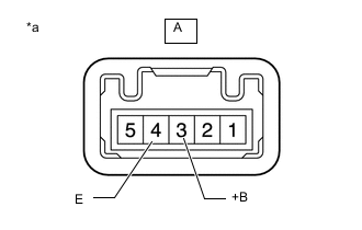
*a Component without harness connected
(Brake Hold Switch)
Turn the power switch off.
-
Disconnect the A brake hold switch connector.
-
Measure the resistance according to the value(s) in the table below.
Standard Resistance Tester Connection Condition Specified Condition A-3 (+B) - A-4 (E) Switch pushed Below 1 Ω A-3 (+B) - A-4 (E) Switch not pushed 10 kΩ or higher Result Proceed to OK NG
NG
REPLACE BRAKE HOLD SWITCH Click here
OK
-
-
INSPECT SWITCH WIRE
-
Disconnect the G7 switch wire.
-
Disconnect the A brake hold switch connector.
-
Measure the resistance according to the value(s) in the table below.
Standard Resistance Tester Connection Condition Specified Condition G7-3(+B) - A-3(+B) Always Below 1 Ω G7-3(+B) or A-3(+B) - Body ground Always 10 kΩ or higher G7-6(E) - A-4(E) Always Below 1 Ω G7-6(E) or A-4(E) - Body ground Always 10 kΩ or higher Result Proceed to OK NG
NG
REPLACE SWITCH WIRE Click here
OK
-
-
CHECK HARNESS AND CONNECTOR (SKID CONTROL ECU ASSEMBLY - SWITCH WIRE)
-
Disconnect the A12 skid control ECU assembly connector.
-
Measure the resistance according to the value(s) in the table below.
Standard Resistance Tester Connection Condition Specified Condition A12-14 (HZRI) - G7-3 (+B) Always Below 1 Ω A12-14 (HZRI) or G7-3 (+B) - Body ground Always 10 kΩ or higher G7-6 (E) - Body ground Always Below 1 Ω Result Proceed to OK NG
NG
REPAIR BRAKE HOLD SWITCH Click here
OK
-
-
INSPECT FRONT DOOR COURTESY LIGHT SWITCH ASSEMBLY
-
Turn on the interior lights and check that they illuminate, and then set the switch so that the lights illuminate when the door is opened.
-
Check that the lights illuminate when the driver side door is opened.
OK The interior lights illuminate when the driver side door is opened. Result Proceed to OK NG
NG
INSPECT LIGHTING SYSTEM Click here
OK
-
-
CHECK HARNESS AND CONNECTOR (CTY TERMINAL)
-
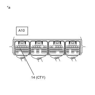
*a Component with harness connected
(Skid Control ECU Assembly)
Measure the voltage and waveform according to the value(s) in the table below.
Standard Voltage Tester Connection Condition Specified Condition A10-14 (CTY) - Body ground Driver door open Below 1 V A10-14 (CTY) - Body ground Driver door closed Pulse generation (waveform 1)
-
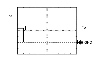
*a Driver door closed *b Driver door open Waveform 1 (Reference)
Item Content Tester Connection A10-14 (CTY) - Body ground Tool Setting 5 V/DIV., 10 ms./DIV. Vehicle Condition Driver door closed → open
Result Proceed to OK NG -
OK
REPLACE SKID CONTROL ECU ASSEMBLY for LHD: Click here
REPLACE SKID CONTROL ECU ASSEMBLY for RHD: Click hereNG
REPAIR OR REPLACE HARNESS OR CONNECTOR (CTY CIRCUIT)
-