Click here
Click here
PROCEDURE
- Click here
INSPECT BRAKE ACTUATOR ASSEMBLY
-
Inspect the solenoid circuit.
-
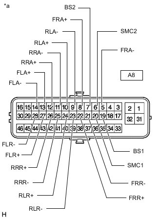
*a Component without harness connected
(Brake Actuator Assembly)
Measure the resistance according to the value(s) in the table below.
Tip:Check the brake actuator assembly when it is cooled down.
Standard Resistance Tester Connection Condition Specified Condition A8-20(SMC1) - A8-19(BS1) Always 15.3 to 17.3 Ω A8-6(SMC2) - A8-7(BS2) Always 15.3 to 17.3 Ω A8-8(FRA+) - A8-5(FRA-) Always 3.6 to 4.2 Ω A8-22(FRR+) - A8-21(FRR-) Always 3.6 to 4.2 Ω A8-13(FLA+) - A8-14(FLA-) Always 3.6 to 4.2 Ω A8-27(FLR+) - A8-28(FLR-) Always 3.6 to 4.2 Ω A8-12(RRA+) - A8-11(RRA-) Always 3.6 to 4.2 Ω A8-10(RLA+) - A8-9(RLA-) Always 3.6 to 4.2 Ω A8-26(RRR+) - A8-25(RRR-) Always 4.4 to 5.0 Ω A8-24(RLR+) - A8-23(RLR-) Always 4.4 to 5.0 Ω If the result is not as specified, replace the brake actuator assembly.
-
-