| DTC Code | DTC Name |
|---|---|
| C1235 | Foreign Object is Attached on Tip of Front Speed Sensor RH |
| C1236 | Foreign Object is Attached on Tip of Front Speed Sensor LH |
| C1238 | Foreign Object is Attached on Tip of Rear Speed Sensor RH |
| C1239 | Foreign Object is Attached on Tip of Rear Speed Sensor LH |
DESCRIPTION
When foreign matter adheres to a speed sensor tip or speed sensor rotor, these DTCs are stored. The presence of foreign matter can be judged when an abnormal waveform is received from a sensor.
These DTCs may also be detected when a malfunction occurs in the connector terminals or wire harness of the speed sensor circuit.
When C1464, C1465, C1466, and/or C1467 are output together with C1235, C1236, C1238, and/or C1239, inspect and repair the trouble areas indicated by C1464, C1465, C1466, and/or C1467 first.
| DTC No. | Detection Item | INF Code | DTC Detection Condition | Trouble Area | Note |
|---|---|---|---|---|---|
| C1235 | Foreign Object is Attached on Tip of Front Speed Sensor RH | 302 | Either of the following is detected:
|
|
- |
| C1236 | Foreign Object is Attached on Tip of Front Speed Sensor LH | 303 | Either of the following is detected:
|
|
- |
| C1238 | Foreign Object is Attached on Tip of Rear Speed Sensor RH | 304 | Either of the following is detected:
|
|
- |
| C1239 | Foreign Object is Attached on Tip of Rear Speed Sensor LH | 305 | Either of the following is detected:
|
|
- |
-
DTC C1235 is for the front speed sensor RH.
-
DTC C1236 is for the front speed sensor LH.
-
DTC C1238 is for the rear speed sensor RH.
-
DTC C1239 is for the rear speed sensor LH.
| Vehicle Condition | |||
|---|---|---|---|
| Pattern 1 | Pattern 2 | ||
| Diagnosis Condition | The vehicle speed is 20 km/h (12 mph) or more | ○ | - |
| The vehicle speed is 10 km/h (6 mph) or more | - | ○ | |
| Malfunction Status | Noise occurs in the speed sensor signal waveform | ○ | - |
| Noise is input 1 time per rotor revolution | - | ○ | |
| Detection Time | 5 seconds or more | 15 seconds or more | |
| Number of Trips | 1 trip | 1 trip | |
WIRING DIAGRAM
Refer to DTCs C1464, C1465, C1466 and C1467.
for Front:Click here
for Rear:Click here
CAUTION / NOTICE / HINT
When replacing the skid control ECU assembly, perform initialization and calibration of the linear solenoid valve.
PROCEDURE
- Click here
CHECK DTC
-
Check the output DTCs .
- Chassis > ABS/VSC/TRC > Trouble Codes
-
-
Result Result Proceed to DTC C1235 or C1236 is output. (for 2WD) A DTC C1235 or C1236 is output. (for AWD) B DTC C1238 or C1239 is output. C DTCs C1464 or C1465 are output simultaneously. D DTCs C1466 or C1467 are output simultaneously. E
- AClick here
- BClick here
- CClick here
- D
REPAIR CIRCUITS INDICATED BY OUTPUT DTCSClick here
- E
REPAIR CIRCUITS INDICATED BY OUTPUT DTCSClick here
-
-
*A for RH *B for LH *1 Front Skid Control Sensor Wire *a Front view of wire harness connector (to Vehicle Side Connector) *b Front view of wire harness connector (to Sensor Side Connector)Click here
INSPECT FRONT SKID CONTROL SENSOR WIRE
-
Make sure that there is no looseness at the locking part and the connecting part of the connectors.
-
Remove the front skid control sensor wire.
-
Measure the resistance according to the value(s) in the table below.
Standard Resistance Table 5. for RH Tester Connection Condition Specified Condition z21 -1 (FR+) - A25 -5 (FR+) Always Below 1 Ω z21 -1 (FR+) or A25 -5 (FR+) - Body ground and other terminals Always 10 MΩ or higher z21 -2 (FR-) - A25 -1 (FR-) Always Below 1 Ω z21 -2 (FR-) or A25 -1 (FR-) - Body ground and other terminals Always 10 MΩ or higher Table 6. for LH Tester Connection Condition Specified Condition A16 -2 (FL+) - AA3 -3 Always Below 1 Ω A16 -2 (FL+) or AA3 -3 - Body ground and other terminals Always 10 MΩ or higher A16 -1 (FL-) - AA3 -1 Always Below 1 Ω A16 -1 (FL-) or AA3 -1 - Body ground and other terminals Always 10 MΩ or higher Result Proceed to OK NG
- OKClick here
- NG
REPLACE FRONT SKID CONTROL SENSOR WIREClick here
-
- Click here
CHECK HARNESS AND CONNECTOR (SKID CONTROL ECU ASSEMBLY - FRONT SKID CONTROL SENSOR WIRE)
-
Make sure that there is no looseness at the locking part and the connecting part of the connector.
-
Disconnect the A10 and A12 skid control ECU assembly connectors.
-
Measure the resistance according to the value(s) in the table below.
Standard Resistance Table 7. for RH Tester Connection Condition Specified Condition A10-22 (FR+) - A25-5 (FR+) Always Below 1 Ω A10-22 (FR+) or A25-5 (FR+) - Body ground Always 10 MΩ or higher A10-23 (FR-) - A25-1 (FR-) Always Below 1 Ω A10-23 (FR-) or A25-1 (FR-) - Body ground Always 10 MΩ or higher Table 8. for LH Tester Connection Condition Specified Condition A12-31 (FL+) - AA3 -3 Always Below 1 Ω A12-31 (FL+) or AA3 -3 - Body ground Always 10 MΩ or higher A12-32 (FL-) - AA3 -1 Always Below 1 Ω A12-32 (FL-) or AA3 -1 - Body ground Always 10 MΩ or higher Result Proceed to OK NG
- OK
REPLACE FRONT AXLE HUB SUB-ASSEMBLYClick here
Tip:The front speed sensor and speed sensor rotor are incorporated into the front axle hub sub-assembly.
- NG
REPAIR OR REPLACE HARNESS OR CONNECTOR
-
- Click here
CHECK HARNESS AND CONNECTOR (SKID CONTROL ECU ASSEMBLY - FRONT SPEED SENSOR)
-
Make sure that there is no looseness at the locking part and the connecting part of the connector.
-
Disconnect the A10 and A12 skid control ECU assembly connectors.
-
Measure the resistance according to the value(s) in the table below.
Standard Resistance Table 9. for RH Tester Connection Condition Specified Condition A10-22 (FR+) - A73-5 (FR+) Always Below 1 Ω A10-22 (FR+) or A73-5 (FR+) - Body ground Always 10 MΩ or higher A10-23 (FR-) - A73-1 (FR-) Always Below 1 Ω A10-23 (FR-) or A73-1 (FR-) - Body ground Always 10 MΩ or higher Table 10. for LH Tester Connection Condition Specified Condition A12-31 (FL+) - A72-3 (FL+) Always Below 1 Ω A12-31 (FL+) or A72-3 (FL+) - Body ground Always 10 MΩ or higher A12-32 (FL-) - A72-1 (FL-) Always Below 1 Ω A12-32 (FL-) or A72-1 (FL-) - Body ground Always 10 MΩ or higher Result Proceed to OK NG
- OKClick here
- NG
REPAIR OR REPLACE HARNESS OR CONNECTOR
-
- Click here
CHECK FRONT SPEED SENSOR
-
Check the speed sensor tip.
OK The sensor tip is free of oil and foreign matter. Result Proceed to OK NG
- OKClick here
- NG
CLEAN FRONT SPEED SENSOR
-
- Click here
CHECK FRONT AXLE HUB SUB-ASSEMBLY
-
Check the speed sensor rotor (front axle hub sub-assembly).
OK The speed sensor rotor is free of scratches, oil, and foreign matter. Tip:The speed sensor rotor is incorporated into the rear front axle hub sub-assembly.
Result Result Proceed to OK A Foreign matter and oil present B Damage present C
- A
REPLACE FRONT SPEED SENSORClick here
- B
CLEAN SPEED SENSOR ROTOR
- C
REPLACE FRONT AXLE HUB SUB-ASSEMBLYClick here
-
- Click here
INSPECT SKID CONTROL SENSOR WIRE
-
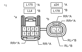
*A for RH *B for LH *1 Front view of skid control sensor wire *a Front view of wire harness connector
(to Vehicle Side Connector)
*b Front view of wire harness connector
(to Sensor Side Connector)
Make sure that there is no looseness at the locking part and the connecting part of the connectors.
-
Remove the skid control sensor wire.
-
Measure the resistance according to the value(s) in the table below.
Standard Resistance Table 11. for RH Tester Connection Condition Specified Condition z24 -2 (RR+) - L175 -3 (RR+) Always Below 1 Ω z24 -2 (RR+) - L175 -4 (RR-) Always 10 MΩ or higher z24 -2 (RR+) or L175 -3 (RR+) - Body ground Always 10 MΩ or higher z24 -1 (RR-) - L175 -4 (RR-) Always Below 1 Ω z24 -1 (RR-) - L175 -3 (RR+) Always 10 MΩ or higher z24 -1 (RR-) or L175 -4 (RR-) - Body ground Always 10 MΩ or higher Table 12. for LH Tester Connection Condition Specified Condition L178 -2 (RL+) - LL4 -3 Always Below 1 Ω L178 -2 (RL+) - LL4 -4 Always 10 MΩ or higher L178 -2 (RL+) or LL4 -3 - Body ground Always 10 MΩ or higher L178 -1 (RL-) - LL4 -4 Always Below 1 Ω L178 -1 (RL-) - LL4 -3 Always 10 MΩ or higher L178 -1 (RL-) or LL4 -4 - Body ground Always 10 MΩ or higher Result Proceed to OK NG
- OKClick here
- NG
REPLACE SKID CONTROL SENSOR WIREClick here
-
- Click here
CHECK HARNESS AND CONNECTOR (SKID CONTROL ECU ASSEMBLY - SKID CONTROL SENSOR WIRE)
-
Make sure that there is no looseness at the locking part and the connecting part of the connector.
-
Disconnect the A9 and A11 skid control ECU assembly connectors.
-
Measure the resistance according to the value(s) in the table below.
Standard Resistance Table 13. for RH Tester Connection Condition Specified Condition A13-22 (RR+) - L175-3 (RR+) Always Below 1 Ω A13-22 (RR+) or L175-3 (RR+) - Body ground Always 10 MΩ or higher A13-21 (RR-) - L175-4 (RR-) Always Below 1 Ω A13-21 (RR-) or L175-4 (RR-) - Body ground Always 10 MΩ or higher Table 14. for LH Tester Connection Condition Specified Condition A11-34 (RL+) - LL4 -3 Always Below 1 Ω A11-34 (RL+) or LL4 -3 - Body ground Always 10 MΩ or higher A11-35 (RL-) - LL4 -4 Always Below 1 Ω A11-35 (RL-) or LL4 -4 - Body ground Always 10 MΩ or higher Result Proceed to OK NG
- OKClick here
- NG
REPAIR OR REPLACE HARNESS OR CONNECTOR
-
- Click here
CHECK REAR SPEED SENSOR
-
Check the speed sensor tip.
OK The sensor tip is free of oil and foreign matter. Result Proceed to OK NG
- OKClick here
- NG
CLEAN REAR SPEED SENSOR
-
- Click here
CHECK REAR AXLE HUB AND BEARING ASSEMBLY
-
Check the speed sensor rotor (rear axle hub and bearing assembly).
OK The speed sensor rotor is free of scratches, oil, and foreign matter. Tip:The speed sensor rotor is incorporated into the rear axle hub and bearing assembly.
Result Result Proceed to OK A Foreign matter and oil present B Damage present C
- A
REPLACE REAR SPEED SENSORClick here
- B
CLEAN SPEED SENSOR ROTOR
- C
REPLACE REAR AXLE HUB AND BEARING ASSEMBLYClick here
-