TIRE PRESSURE WARNING SYSTEM, Diagnostic DTC:C2179
| DTC Code | DTC Name |
|---|---|
| C2179 | Tire Pressure Monitor ECU Communication Stop |
DESCRIPTION
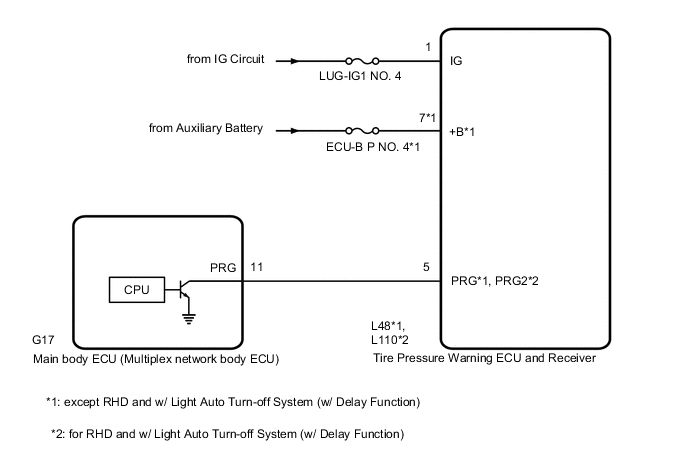
The main body ECU (multiplex network body ECU) sends signals to the tire pressure warning ECU and receiver via a direct line.
| DTC No. | Detection Item | DTC Detection Condition | Trouble Area | Note |
|---|---|---|---|---|
| C2179 | Tire Pressure Monitor ECU Communication Stop | Communication between the main body ECU (multiplex network body ECU) and tire pressure warning ECU and receiver is interrupted for 10 seconds or more. |
|
- |
-
*: except RHD and w/ Light Auto Turn-off System (w/ Delay Function)
WIRING DIAGRAM
CAUTION / NOTICE / HINT
Note
-
When replacing the tire pressure warning ECU and receiver, first use the GTS to record all of the current IDs and registered tires with transmitters (4 or 5 tires) of the tire pressure warning valve and transmitter registered to the tire pressure warning ECU and receiver.
-
It is necessary to perform initialization after registration Click here of the transmitter IDs into the tire pressure warning ECU and receiver after the ECU has been replaced.
-
Before replacing the main body ECU (multiplex network body ECU), refer to Service Bulletin.
Tech Tips
Inspect the fuses for circuits related to this system before performing the following inspection procedure.
PROCEDURE
-
INSPECT MAIN BODY ECU (MULTIPLEX NETWORK BODY ECU) (OUTPUT WAVEFORM)
-
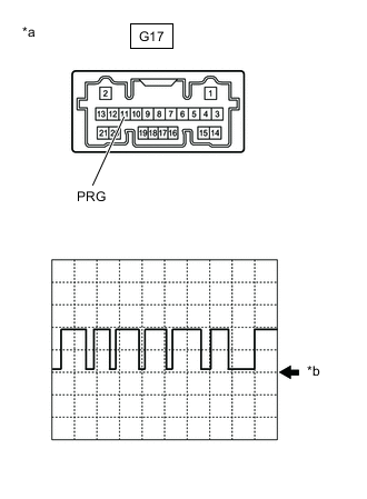
*a Component with harness connected
(Main Body ECU (Multiplex Network Body ECU))
*b GND Using an oscilloscope, check the waveform.
Note
With the connector connected, check from the backside of the connector.
Standard Voltage Tester Connection Tool Setting Range Condition Specified Condition G17-11 (PRG) - Body ground 5 V/DIV.5 ms./DIV. Power switch on (IG) Waveform generation Result Result Proceed to Waveform is as shown in the illustration. (Waveform alternates between 9.8 V or higher and 1.2 V or less) A Waveform does not change from 9.8 V or higher B Waveform does not change from 1.2 V or less C
A 
REPLACE TIRE PRESSURE WARNING ECU AND RECEIVER except RHD and w/ Light Auto Turn-off System (w/ Delay Function): REPLACE TIRE PRESSURE WARNING ECU AND RECEIVER Click here
REPLACE TIRE PRESSURE WARNING ECU AND RECEIVER for RHD and w/ Light Auto Turn-off System (w/ Delay Function): REPLACE TIRE PRESSURE WARNING ECU AND RECEIVER Click hereB
REPLACE MAIN BODY ECU (MULTIPLEX NETWORK BODY ECU) Click here
C 
-
-
CHECK TERMINAL VOLTAGE (TIRE PRESSURE WARNING ECU AND RECEIVER OUTPUT)
-
Disconnect the G17 main body ECU (multiplex network body ECU) connector.
-
Measure the voltage according to the value(s) in the table below.
Standard Voltage Tester Connection Condition Specified Condition G17-11 (PRG) - Body ground Power switch on (IG) 9.8 V or higher Result Proceed to OK NG
OK
REPLACE MAIN BODY ECU (MULTIPLEX NETWORK BODY ECU) Click here
NG
-
-
CHECK HARNESS AND CONNECTOR (TIRE PRESSURE WARNING ECU AND RECEIVER - MAIN BODY ECU (MULTIPLEX NETWORK BODY ECU))
-
Turn the power switch off.
-
Disconnect the L48*1 or L110*2 tire pressure warning ECU and receiver connector.
-
*1: except RHD and w/ Light Auto Turn-off System (w/ Delay Function)
-
*2: for RHD and w/ Light Auto Turn-off System (w/ Delay Function)
-
-
Measure the resistance according to the value(s) in the table below.
Standard Resistance except RHD and w/ Light Auto Turn-off System (w/ Delay Function): Tester Connection Condition Specified Condition L48-5 (PRG) - G17-11 (PRG) Always Below 1 Ω L48-5 (PRG) or G17-11 (PRG) - Body ground Always 10 kΩ or higher Standard Resistance for RHD and w/ Light Auto Turn-off System (w/ Delay Function): Tester Connection Condition Specified Condition L110-5 (PRG2) - G17-11 (PRG) Always Below 1 Ω L110-5 (PRG2) or G17-11 (PRG) - Body ground Always 10 kΩ or higher Result Proceed to OK NG
NG
REPAIR OR REPLACE HARNESS OR CONNECTOR
OK
-
-
CHECK HARNESS AND CONNECTOR (POWER SUPPLY - TIRE PRESSURE WARNING ECU AND RECEIVER)
-
Measure the voltage according to the value(s) in the table below.
Standard Voltage except RHD and w/ Light Auto Turn-off System (w/ Delay Function): Tester Connection Condition Specified Condition L48-7 (+B) - Body ground Always 10 to 16 V L48-1 (IG) - Body ground Power switch on (IG) 10 to 16 V Standard Voltage for RHD and w/ Light Auto Turn-off System (w/ Delay Function): Tester Connection Condition Specified Condition L110-1 (IG) - Body ground Power switch on (IG) 10 to 16 V Result Proceed to OK NG
OK
REPLACE TIRE PRESSURE WARNING ECU AND RECEIVER except RHD and w/ Light Auto Turn-off System (w/ Delay Function): REPLACE TIRE PRESSURE WARNING ECU AND RECEIVER Click here
REPLACE TIRE PRESSURE WARNING ECU AND RECEIVER for RHD and w/ Light Auto Turn-off System (w/ Delay Function): REPLACE TIRE PRESSURE WARNING ECU AND RECEIVER Click hereNG
REPAIR OR REPLACE HARNESS OR CONNECTOR
-