FRONT SUSPENSION MEMBER(for AWD) INSTALLATION

PROCEDURE
-
INSTALL FRONT STABILIZER BAR
-
INSTALL RACK AND PINION POWER STEERING GEAR ASSEMBLY
-
TEMPORARILY TIGHTEN FRONT LOWER SUSPENSION ARM ASSEMBLY LH
-
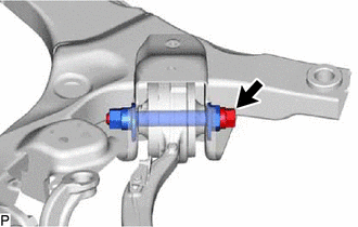
Temporarily install the front lower suspension arm assembly LH, and insert the front suspension toe adjust cam sub-assembly from the rear of the vehicle.
-
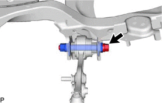
Install the bolt, front No.2 suspension toe adjust plate and temporarily install the bolt.
Tech Tips
After stabilizing the suspension, tighten the bolt.
-
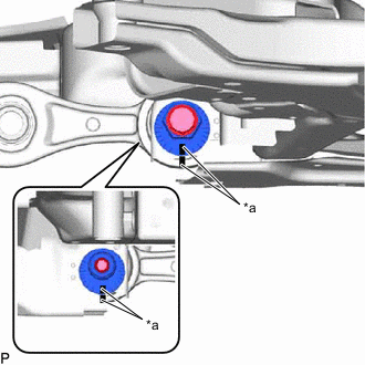
*a Matchmark Align the matchmarks of the front suspension toe adjust cam sub-assembly, front No.2 suspension toe adjust plate and front frame assembly.
-
-
TEMPORARILY TIGHTEN FRONT LOWER SUSPENSION ARM ASSEMBLY RH
Tech Tips
Perform the same procedure as for the LH side.
-
INSTALL FRONT STABILIZER LINK ASSEMBLY LH
-
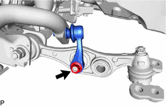
Install the front stabilizer link assembly LH with the nut.
Tech Tips
If the ball joint turns together with the nut, use a 8 mm hexagon wrench to hold the stud bolt.
- Torque:
- 150 N*m { 1530 kgf*cm, 111 ft.*lbf }
-
-
INSTALL FRONT STABILIZER LINK ASSEMBLY RH
Tech Tips
Perform the same procedure as for the LH side.
-
TEMPORARILY TIGHTEN FRONT LOWER SHOCK ABSORBER BRACKET SUB-ASSEMBLY LH
-
Install the front lower shock absorber bracket sub-assembly LH to the front lower suspension arm assembly LH.
-
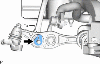
*a Protrusion Align the protrusion of the front upper shock absorber bracket plate with cutout of the front lower shock absorber bracket sub-assembly LH, and temporarily install the nut.
Tech Tips
Fully tighten the nut after stabilizing the suspension.
-
-
TEMPORARILY TIGHTEN FRONT LOWER SHOCK ABSORBER BRACKET SUB-ASSEMBLY RH
Tech Tips
Perform the same procedure as for the LH side.
-
TEMPORARILY TIGHTEN LOWER NO.2 SUSPENSION ARM ASSEMBLY LH
-
Temporarily install the lower No. 2 suspension arm assembly LH, and insert the front suspension toe adjust cam sub-assembly from the rear of the vehicle.
-
Install the bolt, front No.2 suspension toe adjust plate and temporarily install the bolt.
Tech Tips
After stabilizing the suspension, tighten the bolt.
-
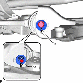
*a Matchmark Align the matchmarks of the front suspension toe adjust cam sub-assembly, front No.2 suspension toe adjust plate and front frame assembly.
-
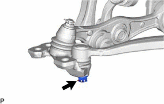
Install the lower No. 2 suspension arm assembly LH to the front lower ball joint assembly LH with the nut.
- Torque:
- 145 N*m { 1479 kgf*cm, 107 ft.*lbf }
-
Install a new clip.
Note
Further tighten the nut up to 60° if the holes for the clip are not aligned.
-
-
TEMPORARILY TIGHTEN LOWER NO.2 SUSPENSION ARM ASSEMBLY RH
Tech Tips
Perform the same procedure as for the LH side.
-
INSTALL FRONT ENGINE MOUNTING INSULATOR
-
CONNECT FRONT FRAME ASSEMBLY
-
INSTALL ENGINE AND TRANSMISSION
-
STABILIZE SUSPENSION
-
FULLY TIGHTEN FRONT LOWER SUSPENSION ARM ASSEMBLY LH
-
FULLY TIGHTEN FRONT LOWER SUSPENSION ARM ASSEMBLY RH
Tech Tips
Perform the same procedure as for the LH side.
-
FULLY TIGHTEN FRONT LOWER SHOCK ABSORBER BRACKET SUB-ASSEMBLY LH
-
FULLY TIGHTEN FRONT LOWER SHOCK ABSORBER BRACKET SUB-ASSEMBLY RH
Tech Tips
Perform the same procedure as for the LH side.
-
FULLY TIGHTEN LOWER NO.2 SUSPENSION ARM ASSEMBLY LH
-
FULLY TIGHTEN LOWER NO.2 SUSPENSION ARM ASSEMBLY RH
Tech Tips
Perform the same procedure as for the LH side.