POWER TRUNK LID SYSTEM Power Trunk Lid does not Operate Using Cabin Switch
DESCRIPTION
The trunk and fuel switch assembly (luggage door opening switch) signal is sent to the luggage closer motor assembly.
If the power trunk lid does not operate using the trunk and fuel (luggage door opening switch), a trunk and fuel (luggage door opening switch) circuit malfunction is a possible cause.
WIRING DIAGRAM
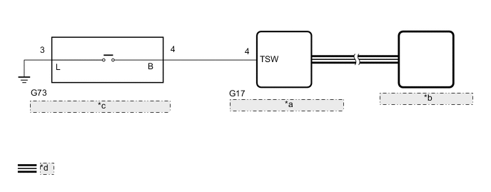
| *a | Main Body ECU (Multiplex Network Body ECU) |
| *b | Luggage Closer Motor Assembly |
| *c | Trunk and Fuel Switch Assembly (Luggage Door Opening Switch) |
| *d | CAN Communication Line |
CAUTION / NOTICE / HINT
Note
-
If the replacement, removal and installation of the luggage closer motor assembly or disconnection of the connectors of the luggage closer motor assembly has been performed, initialize the power trunk lid system.
-
Before replacing the main body ECU (multiplex network body ECU), refer to Service Bulletin.
PROCEDURE
-
READ VALUE USING GTS
-
Read the Data List according to the display on the GTS.
Body Electrical > Main Body > Data ListTester Display Measurement Item Range Normal Condition Diagnostic Note Trunk/BDoor Open SW Trunk and fuel switch assembly (luggage door opening switch) signal OFF or ON OFF: Trunk and fuel switch assembly (luggage door opening switch) off
ON: Trunk and fuel switch assembly (luggage door opening switch) on
-
Body Electrical > Main Body > Data ListTester Display Trunk/BDoor Open SW OK The Data List item changes according to the operation of the trunk and fuel switch assembly (luggage door opening switch). Result Proceed to OK NG
OK 
REPLACE MAIN BODY ECU (MULTIPLEX NETWORK BODY ECU) Click here
NG 
-
-
INSPECT TRUNK AND FUEL SWITCH ASSEMBLY (LUGGAGE DOOR OPENING SWITCH)
-
Remove the trunk and fuel switch assembly (luggage door opening switch).
-
Inspect the trunk and fuel switch assembly (luggage door opening switch).
Result Proceed to OK NG
NG
REPLACE TRUNK AND FUEL SWITCH ASSEMBLY (LUGGAGE DOOR OPENING SWITCH) Click here
OK
-
-
CHECK HARNESS AND CONNECTOR (TRUNK AND FUEL SWITCH ASSEMBLY [LUGGAGE DOOR OPENING SWITCH] - MAIN BODY ECU [MULTIPLEX NETWORK BODY ECU] AND BODY GROUND)
-
Disconnect the G73 trunk and fuel switch assembly (luggage door opening switch) connector.
-
Disconnect the G17 main body ECU (multiplex network body ECU) connector.
-
Measure the resistance according to the value(s) in the table below.
Standard Resistance Tester Connection Condition Specified Condition G73-4 (B) - G17-4 (TSW) Always Below 1 Ω G73-3 (L) - Body ground Always Below 1 Ω G73-4 (B) or G17-4 (TSW) - Body ground Always 10 kΩ or higher Result Proceed to OK NG
OK
REPLACE MAIN BODY ECU (MULTIPLEX NETWORK BODY ECU) Click here
NG
REPAIR OR REPLACE HARNESS OR CONNECTOR
-