SLIDING ROOF SWITCH ASSEMBLY INSPECTION
PROCEDURE
-
INSPECT MAP LIGHT ASSEMBLY
-
Check the sliding roof switch (map light assembly).
-
Measure the resistance between each terminal of the spiral cable sub-assembly according to the value (s) in the table below.
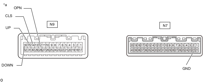
*a Component without harness connected
(Sliding Roof Switch (Map Light Assembly))
- - Tech Tips
If the result is not as specified, replace the sliding roof switch (map light assembly).
Standard Resistance Tester Connection Condition Specified Condition N9-15(UP) - N7-22(GND) UP switch ON 100 Ω or less N9-15(UP) - N7-22(GND) UP switch OFF 1 kΩ or higher N9-16(DOWN) - N7-22(GND) DOWN switch ON 100 Ω or less N9-16(DOWN) - N7-22(GND) DOWN switch OFF 1 kΩ or higher N9-12(OPN) - N7-22(GND) OPEN switch ON 100 Ω or less N9-12(OPN) - N7-22(GND) OPEN switch OFF 1 kΩ or higher N9-14(CLS) - N7-22(GND) CLOSE switch ON 100 Ω or less N9-14(CLS) - N7-22(GND) CLOSE switch OFF 1 kΩ or higher
-
-