POWER TRUNK LID SYSTEM TERMINALS OF ECU
-
CHECK LUGGAGE CLOSER MOTOR ASSEMBLY
-
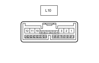
Disconnect the L10 luggage closer motor assembly connector.
-
Measure the voltage and resistance according to the value(s) in the table below.
Terminal No. (Symbol) Wiring Color Terminal Description Condition Specified Condition L10-8 (IG) - Body ground B - Body ground IG power supply Power switch on (IG) 11 to 14 V Power switch off Below 1 V L10-10 (ECUB) - Body ground LA-L - Body ground Auxiliary battery power supply Power switch off 11 to 14 V L10-11 (GND) - Body ground W-B - Body ground Ground Always Below 1 Ω L10-12 (B) - Body ground B - Body ground Auxiliary battery power supply Power switch off 11 to 14 V -
Reconnect the L10 luggage closer motor assembly connector.
-
Measure the voltage, resistance according and waveform to the value(s) in the table below.
Terminal No. (Symbol) Wiring Color Terminal Description Condition Specified Condition L10-1 (LCM-) - Body ground G - Body ground Luggage closer motor assembly (door lock motor) circuit Power trunk lid close operating 11 to 14 V Power trunk lid not operating Below 1 V L10-2 (LCM+) - Body ground B - Body ground Luggage closer motor assembly (door lock motor) circuit Power trunk lid open operating 11 to 14 V Power trunk lid not operating Below 1 V L10-4 (LDDN) - Body ground BE - Body ground Door control switch signal Door control switch on Below 1 V Door control switch off 11 to 14 V L10-7 (HAF) - Body ground V - Body ground Luggage closer motor assembly (half latch switch) signal Luggage closer motor assembly detecting a luggage compartment door ajar 11 to 14 V Luggage closer motor assembly not detecting a luggage compartment door ajar Below 1 V L10-16 (CSG) - Body ground L - Body ground Luggage closer motor assembly (door sensor) ground Always Below 1 Ω L10-17 (CS2) - Body ground B - Body ground Luggage closer motor assembly (door sensor) signal Luggage compartment door closer operating Pulse generation
(See waveform 1)
L10-18 (CS1) - Body ground G - Body ground Luggage closer motor assembly (door sensor) signal Luggage compartment door closer operating Pulse generation
(See waveform 2)
L10-19 (CSV) - Body ground GR - Body ground Luggage closer motor assembly (door sensor) power supply Always 7 V or higher L10-20 (PAWL) - Body ground R - Body ground Luggage closer motor assembly (pawl switch) signal Luggage closer motor assembly detecting a luggage compartment door ajar Below 1 V Luggage closer motor assembly not detecting a luggage compartment door ajar Pulse generation L10-21 (SWG) - Body ground W - Body ground Luggage closer motor assembly (each switch) ground Always Below 1 Ω L10-24 (KSIN) - Body ground* G - Body ground Kick detection signal Kick door control sensor not detecting a foot → detecting a foot Pulse generation
(See waveform 3)
*: w/ Hands Free Power Trunk Lid
-
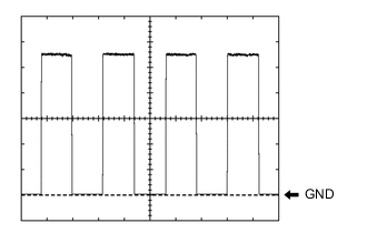
Using an oscilloscope, check waveform 1.
Waveform 1 (Reference) Item Condition Tester connection L10-17 (CS2) - Body ground Tool setting 2V/DIV, 10 ms/DIV. Vehicle condition Luggage compartment door closer operating Tech Tips
The period changes in accordance to the speed at which the luggage compartment door is opened and closed.
-
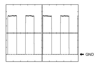
Using an oscilloscope, check waveform 2.
Waveform 2 (Reference) Item Condition Tester connection L10-18 (CS1) - Body ground Tool setting 2V/DIV, 10 ms/DIV. Vehicle condition Luggage compartment door closer operating Tech Tips
The period changes in accordance to the speed at which the luggage compartment door is opened and closed.
-
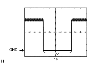
*a Kick detection signal Using an oscilloscope, check waveform 3.
Waveform 3 (Reference) Item Condition Tester connection L10-24 (KSIN) - Body ground Tool setting 2V/DIV, 50 ms/DIV. Vehicle condition Kick door control sensor not detecting a foot → detecting a foot
-
-
-
CHECK INSTRUMENT PANEL JUNCTION BLOCK ASSEMBLY AND MAIN BODY ECU (MULTIPLEX NETWORK BODY ECU)
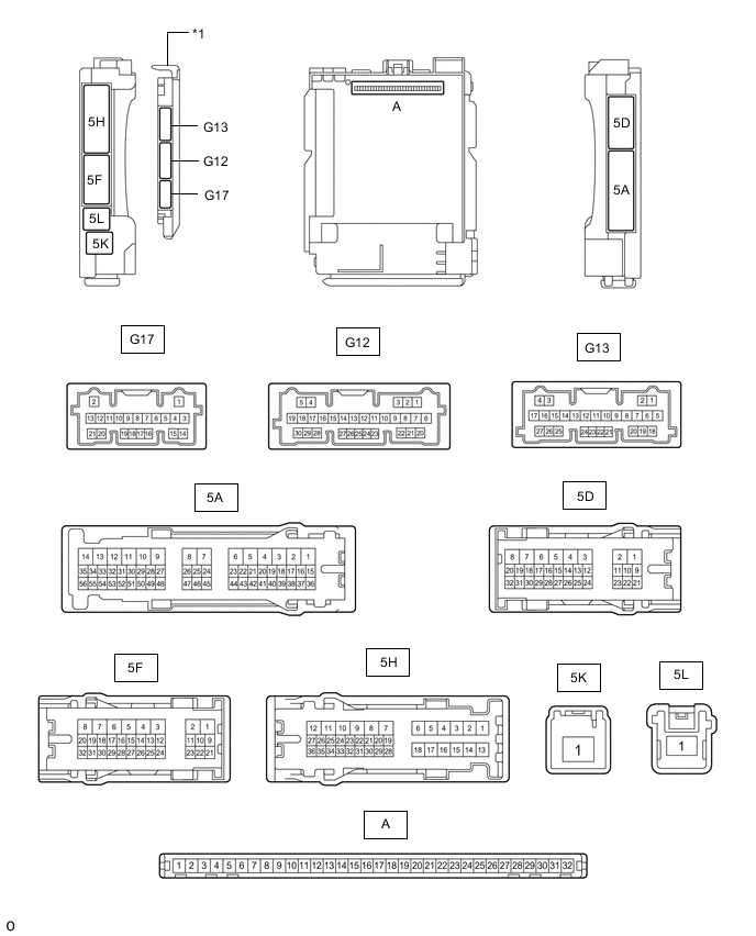
*1 Main Body ECU (Multiplex Network Body ECU) - -
-
Remove the main body ECU (multiplex network body ECU).
-
Connect the instrument panel junction block assembly connectors.
-
Measure the resistance and voltage according to the value(s) in the table below.
Terminal No. (Symbol) Wiring Color Terminal Description Condition Specified Condition A-11 (GND1) - Body ground None - Body ground Ground Always Below 1 Ω A-30 (ACC) - Body ground None - Body ground ACC power supply Power switch on (ACC) 11 to 14 V Power switch off Below 1 V A-31 (BECU) - Body ground None - Body ground Auxiliary battery power supply Power switch off 11 to 14 V A-32 (IG) - Body ground None - Body ground IG power supply Power switch on (IG) 11 to 14 V Power switch off Below 1 V -
Install the main body ECU (multiplex network body ECU) to the instrument panel junction block assembly.
-
Measure the voltage and check for pulses according to the value(s) in the table below.
Terminal No. (Symbol) Wiring Color Terminal Description Condition Specified Condition G17-4 (TSW) - Body ground W - Body ground Trunk and fuel switch assembly (luggage door opening switch) signal Trunk and fuel switch assembly (luggage door opening switch) on Below 1 V Power switch off, all doors closed and trunk and fuel switch assembly (luggage door opening switch) off Pulse generation G12-27 (TMSW) - Body ground B - Body ground Luggage door opening cancel switch assembly signal Luggage door opening cancel switch on Below 1 V Power switch off, all doors closed and luggage door opening cancel switch off 11 to 14 V
-
-
CHECK CERTIFICATION ECU (SMART KEY ECU ASSEMBLY)