SLIDING ROOF SYSTEM TERMINALS OF ECU
-
CHECK SLIDING ROOF ECU (SLIDING ROOF DRIVE GEAR SUB-ASSEMBLY)
-
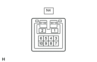
Disconnect the N4 sliding roof drive gear sub-assembly (sliding roof ECU) connector.
-
Measure the resistance and voltage according to the value(s) in the table below.
Tester Connection Wiring Color Terminal Description Condition Specified Condition N4-1 (B) - Body ground LA-G - Body ground Auxiliary battery power supply Power switch off 11 to 14 V N4-2 (E) - Body ground LA-G - Body ground Ground Always Below 1 Ω -
Reconnect the N4 sliding roof drive gear sub-assembly (sliding roof ECU) connector.
-
Measure the voltage according to the value(s) in the table below.
Tester Connection Wiring Color Terminal Description Condition Specified Condition N4-5 (UP) - Body ground G - Body ground Slide roof switch (UP) signal Power switch on (IG), UP switch off → on 11 to 14 V → Below 1 V N4-8 (CLS) - Body ground SB - Body ground Slide roof switch (CLOSE) signal Power switch on (IG), CLOSE switch off → on 11 to 14 V → Below 1 V N4-9 (DWN) - Body ground B - Body ground Slide roof switch (DOWN) signal Power switch on (IG), DOWN switch off → on 11 to 14 V → Below 1 V N4-10 (OPN) - Body ground BR - Body ground Slide roof switch (OPEN) signal Power switch on (IG), OPEN switch off → on 11 to 14 V → Below 1 V -
Measure the pulse according to the value(s) in the table below.
Tester Connection Wiring Color Terminal Description Condition Specified Condition N4-7 (MPX1) - Body ground V - Body ground LIN communication line Power switch on (IG) Pulse generation
-
-
CHECK INSTRUMENT PANEL JUNCTION BLOCK ASSEMBLY AND MAIN BODY ECU (MULTIPLEX NETWORK BODY ECU)