CAUTION / NOTICE / HINT
-
Use the same procedure for RHD and LHD vehicles.
-
The procedure listed below is for LHD vehicles.
PROCEDURE
- Click here
INSTALL GLOVE COMPARTMENT DOOR LOCK CYLINDER ASSEMBLY
-
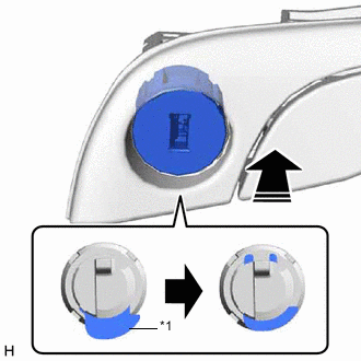
*1 Cylinder Lock 
Install in this Direction With the cylinder lock pressed, insert the glove compartment door lock cylinder assembly into the glove compartment door assembly to install it as shown in the illustration.
-
- Click here
INSTALL GLOVE COMPARTMENT DOOR LOCK ASSEMBLY
-
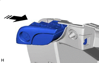
Install in this Direction Set the glove compartment door lock assembly in the direction indicated by the arrow shown in the illustration.
-
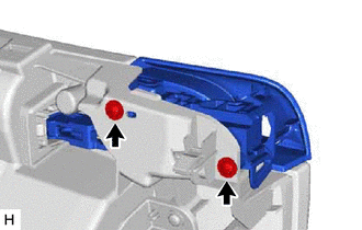
Install the glove compartment door lock assembly with the 2 screws.
-
- Click here
INSTALL COIN BOX ASSEMBLY
-
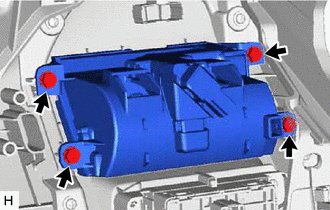
Install the coin box assembly with the 4 screws.
-
- Click here
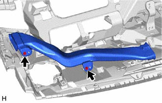
INSTALL NO. 4 HEATER TO REGISTER DUCT SUB-ASSEMBLY
-

Screw <A> Install the No. 4 heater to register duct sub-assembly with the 2 screws <A>.
-
- Click here
INSTALL ION GENERATOR SUB-ASSEMBLY
- Click here
INSTALL NAVIGATION ANTENNA ASSEMBLY WITH BRACKET (for LHD)
- Click here
INSTALL NAVIGATION ANTENNA ASSEMBLY WITH BRACKET (for RHD)
- Click here
INSTALL INSTRUMENT PANEL PASSENGER AIRBAG ASSEMBLY
- Click here
INSTALL NO. 2 INSTRUMENT PANEL WIRE
- Click here
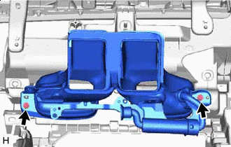
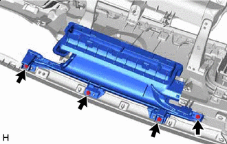
INSTALL DEFROSTER NOZZLE ASSEMBLY
-
w/ Headup Display:
-
Screw <A> Install the defroster nozzle assembly with the 4 screws <A>.
-
-
w/o Headup Display:
-
Screw <A> Install the defroster nozzle assembly with the 5 screws <A>.
-
-
- Click here
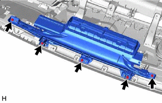
INSTALL NO. 1 SIDE DEFROSTER NOZZLE DUCT
-
w/ Headup Display:
-
Screw <A> Install the No. 1 side defroster nozzle duct with the 2 screws <A>.
-
-
w/o Headup Display:
-
Screw <A> Install the No. 1 side defroster nozzle duct with the 2 screws <A>.
-
-
- Click here
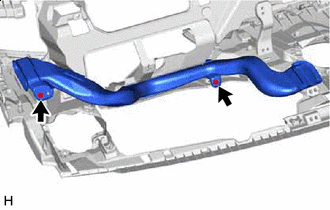
INSTALL NO. 2 SIDE DEFROSTER NOZZLE DUCT
-
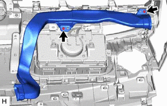
Screw <A> Install the No. 2 side defroster nozzle duct with the 2 screws <A>.
-
- Click here
INSTALL NO. 5 HEATER TO REGISTER DUCT
-
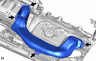
Screw <A> Install the No. 5 heater to register duct with the 4 screws <A>.
-