REAR SUNSHADE SYSTEM Rear Sunshade Shift-linked Function does not Operate when Shift Lever is Moved to R Position
DESCRIPTION
The rear sunshade reverse signal is sent to the rear window shade assembly via the main body ECU (multiplex network body ECU) and operates the rear window shade assembly.
WIRING DIAGRAM
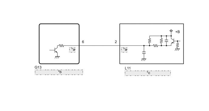
| *a | REV |
| *b | Main Body ECU (Multiplex Network Body ECU) |
| *c | Rear Window Shade Assembly |
CAUTION / NOTICE / HINT
Note
-
If the main body ECU (multiplex network body ECU) is replaced, refer to the Service Bulletin.
-
This function operates when the "R-pos to Rear Sunshade COM" item is set to "ON"using the GTS customization function (The default setting is "ON").
PROCEDURE
-
PERFORM ACTIVE TEST USING GTS
-
Using the GTS, perform the Active Test.
Body Electrical > Main Body > Active TestTester Display Measurement Item Control Range Diagnostic Note Reverse Gear Signal Reverse signal ON / OFF -
Body Electrical > Main Body > Active TestTester Display Reverse Gear Signal Tech Tips
Perform the Active Test while the rear sunshade is fully raised or a raise operation is in progress.
OK Rear sunshade can be lowered. Result Proceed to OK NG
OK 
REPLACE MAIN BODY ECU (MULTIPLEX NETWORK BODY ECU) Click here
NG 
-
-
CHECK HARNESS AND CONNECTOR (REAR WINDOW SHADE ASSEMBLY - MAIN BODY ECU [MULTIPLEX NETWORK BODY ECU])
-
Disconnect the L11 rear window shade assembly connector.
-
Disconnect the G13 main body ECU (multiplex network body ECU) connector.
-
Measure the resistance according to the value(s) in the table below.
Standard Resistance Tester Connection Condition Specified Condition L11-2 (REV) - G13-6 (REV) Always Below 1 Ω Result Proceed to OK NG
NG
REPAIR OR REPLACE HARNESS OR CONNECTOR
OK
-
-
CHECK MAIN BODY ECU (MULTIPLEX NETWORK BODY ECU)
-
Disconnect the G13 main body ECU (multiplex network body ECU) connector.
-
Measure the voltage according to the value(s) in the table below.
Standard Voltage Tester Connection Condition Specified Condition G13-6 (REV) - Body ground Start the hybrid control system, shift lever in not R 11 to 14 V Start the hybrid control system, shift lever in R Below 1 V Result Proceed to OK NG
OK
REPLACE REAR WINDOW SHADE ASSEMBLY Click here
NG
REPLACE MAIN BODY ECU (MULTIPLEX NETWORK BODY ECU) Click here
-