Click here
-
CHECK REAR WINDOW SHADE ASSEMBLY
-
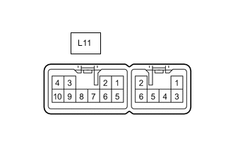
Disconnect the L11 rear window shade assembly connector.
-
Measure the voltage and resistance according to the value(s) in the table below.
Terminal No. (Symbol) Wiring Color Terminal Description Condition Specified Condition L11-3 (B) - Body ground LA-B - Body ground Auxiliary battery power supply Within 60 seconds after power switch turned off, or power switch turned on (IG) again after 60 seconds have elapsed from time power switch turned off 11 to 14 V L11-8 (IG) - Body ground B - Body ground IG power supply Power switch off Below 1 V Power switch on (IG) 11 to 14 V L11-10 (E) - Body ground LA - Body ground Ground Always Below 1 Ω -
Reconnect the L11 rear window shade assembly connector.
-
Measure the voltage according to the value(s) in the table below.
Terminal No. (Symbol) Wiring Color Terminal Description Condition Specified Condition L11-1 (RSW) - Body ground G - Body ground Rear sunshade operation signal
-
Within 60 seconds after power switch turned off or power switch turned on (IG) again after 60 seconds have elapsed from time power switch turned off
-
Rear power seat switch (rear sunshade switch) pushed
Below 1 V
-
Within 60 seconds after power switch turned off, or power switch turned on (IG) again after 60 seconds have elapsed from time power switch turned off
-
Rear power seat switch (rear sunshade switch) not pushed
11 to 14 V L11-2 (REV) - Body ground GR - Body ground Reverse position signal Start the hybrid control system, shift lever in not R 11 to 14 V Start the hybrid control system, shift lever in R Below 1 V L11-5 (SW) - Body ground L - Body ground Rear sunshade operation signal
-
Within 60 seconds after power switch turned off, or power switch turned on (IG) again after 60 seconds have elapsed from time power switch turned off
-
Integration control and panel assembly (rear sunshade switch) pushed
Below 1 V
-
Within 60 seconds after power switch turned off, or power switch turned on (IG) again after 60 seconds have elapsed from time power switch turned off
-
Integration control and panel assembly (rear sunshade switch) not pushed
11 to 14 V -
-
-
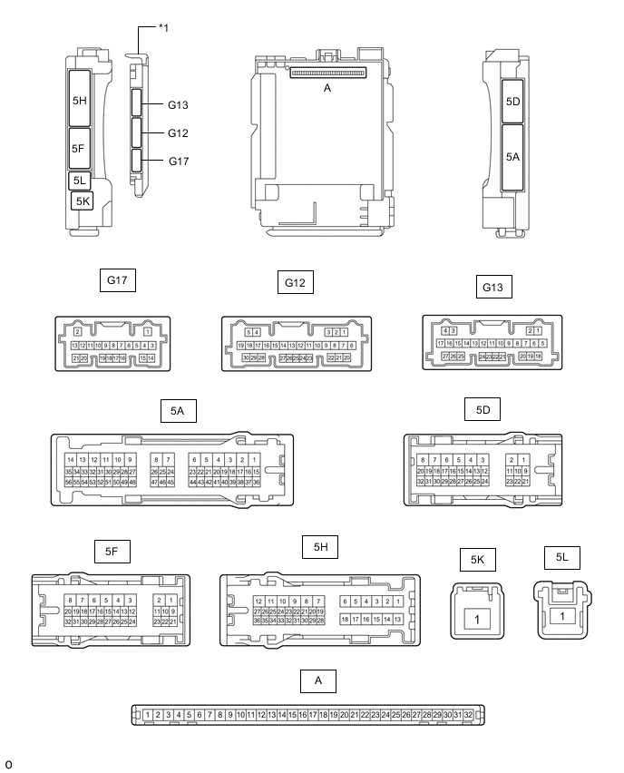
*1 Main Body ECU (Multiplex Network Body ECU) - - CHECK INSTRUMENT PANEL JUNCTION BLOCK ASSEMBLY AND MAIN BODY ECU (MULTIPLEX NETWORK BODY ECU)
-
Remove the main body ECU (multiplex network body ECU).
-
Connect the instrument panel side junction block assembly connectors.
-
Measure the resistance and voltage according to the value(s) in the table below.
Terminal No. (Symbol) Wiring Color Terminal Description Condition Specified Condition A-11 (GND1) - Body ground None - Body ground Ground Always Below 1 Ω A-30 (ACC) - Body ground None - Body ground ACC power supply Power switch on (ACC) 11 to 14 V Power switch off Below 1 V A-31 (BECU) - Body ground None - Body ground Auxiliary battery power supply Power switch off 11 to 14 V A-32 (IG) - Body ground None - Body ground IG power supply Power switch on (IG) 11 to 14 V Power switch off Below 1 V -
Install the main body ECU (multiplex network body ECU) to the instrument panel junction block assembly.
-
Measure the voltage according to the value(s) in the table below.
Terminal No. (Symbol) Wiring Color Terminal Description Condition Specified Condition G13-6 (REV) - Body ground GR - Body ground Reverse position signal Start the hybrid control system, shift lever in not R 11 to 14 V Start the hybrid control system, shift lever in R Below 1 V
-
-
CHECK REAR POWER SEAT SWITCH (w/ Rear Multi Operation Panel System)